Reinforced concrete bridge cantilever bridge wet joint building and pouring intelligent machine

A technology of reinforced concrete bridges and intelligent machinery, applied in bridge construction, bridges, buildings, etc., can solve problems affecting project quality, complicated operation, and unstable concrete, and achieve the effects of wide application range, reduced labor intensity, and improved efficiency

Inactive Publication Date: 2018-03-20
吴秋敏
View PDF0 Cites 9 Cited by
  • Summary
  • Abstract
  • Description
  • Claims
  • Application Information

AI Technical Summary

Problems solved by technology

[0003] In order to solve the above problems, the present invention provides an intelligent machine for constructing and pouring wet joints of reinforced concrete bridge cantilever bridges, which can solve the special working environment existing in the process of concrete pouring for wet joints. Concrete is conveyed with the help of existing mobile equipment. In the process of concrete transportation, it is necessary to manually select suitable equipment according to the width of the joint. Manually conveying and pouring concrete is unstable, and it is easy to cause concrete to splash to a position other than the joint. Manually conveying concrete cannot guarantee the quality of the concrete The uniformity of pouring requires manual vibration and compaction of the poured concrete with the help of existing vibration equipment. During the vibration of wet joint concrete pouring, the reinforcement cage needs to be avoided. The operation is complicated, and the concrete cannot be fully vibrated manually, which cannot ensure The compactness of concrete, the phenomenon of holes in concrete, affecting the quality of the project, and the existence of safety hazards and other problems, can realize the function of automatic pouring of wet joint concrete, without manual vibration of concrete, there is no potential safety hazard, and the uniformity of concrete pouring can be ensured , and has the advantages of simple operation, stable work, resource saving, low labor intensity and high work efficiency

Method used


Image

  • Reinforced concrete bridge cantilever bridge wet joint building and pouring intelligent machine
  • Reinforced concrete bridge cantilever bridge wet joint building and pouring intelligent machine
  • Reinforced concrete bridge cantilever bridge wet joint building and pouring intelligent machine

Examples


Embodiment Construction

[0030] In order to make the technical means, creative features, goals and effects achieved by the present invention easy to understand, the present invention will be further described below in conjunction with specific illustrations.

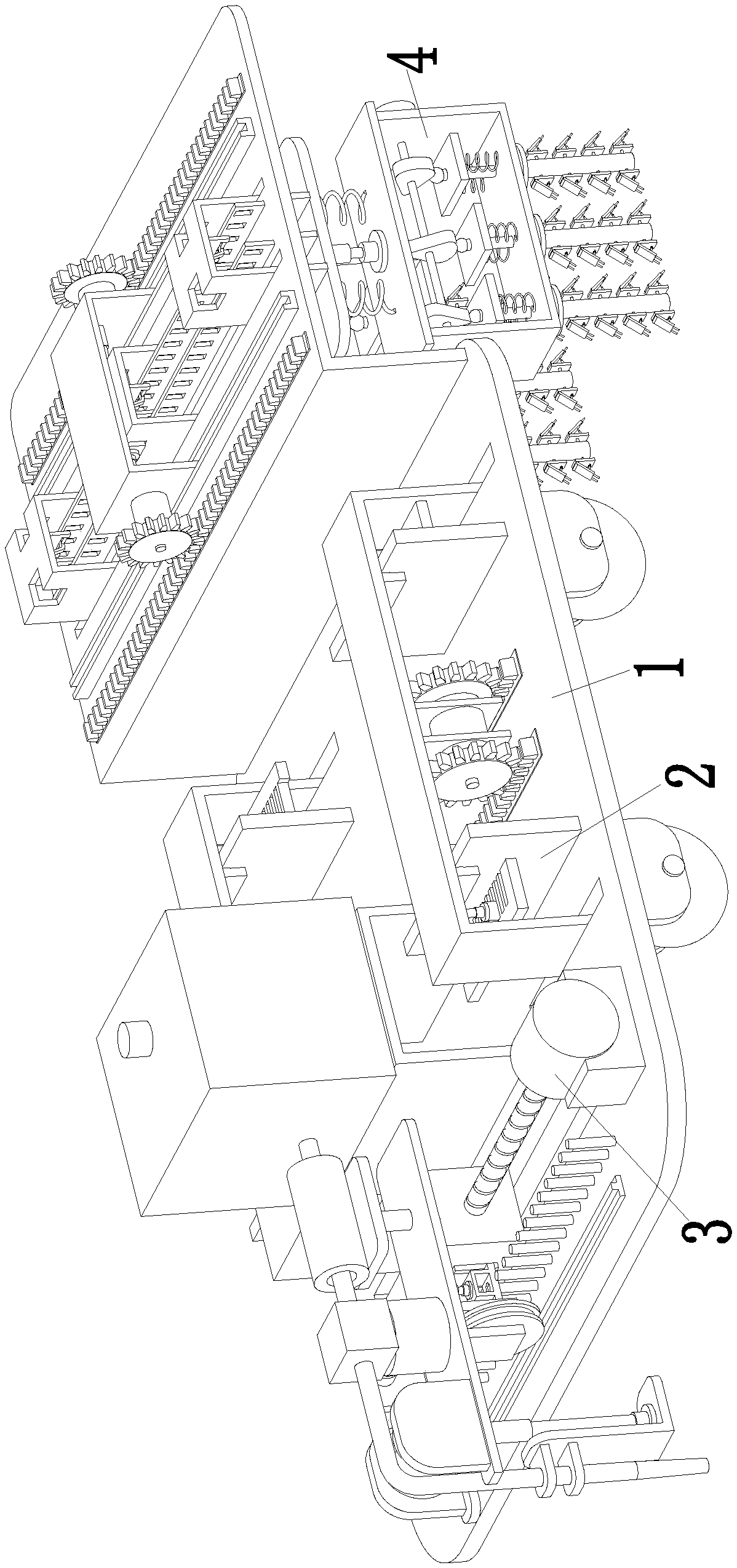
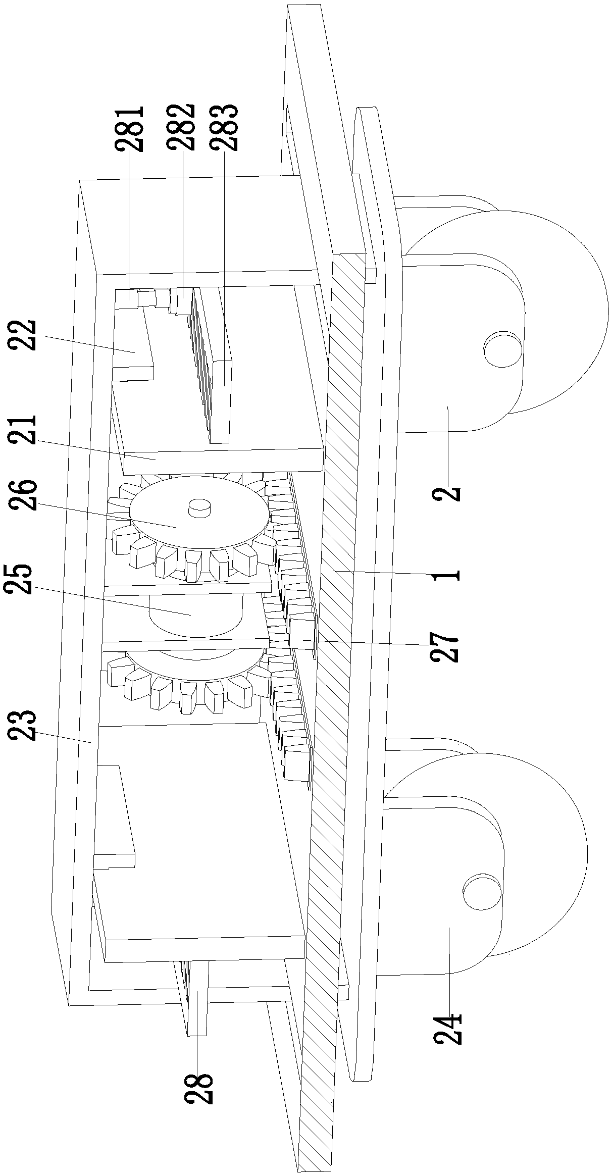
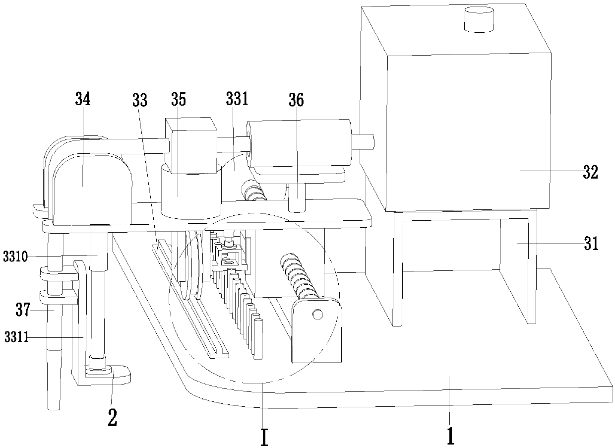
[0031] Such as Figure 1 to Figure 8 As shown, an intelligent machine for constructing and pouring wet joints of reinforced concrete bridge cantilever bridges includes a bottom plate 1. Two pairs of moving adjustment grooves are arranged on the bottom plate 1. The two pairs of moving adjusting grooves are symmetrically located on the left and right sides of the bottom plate 1. The adjustment tanks are equipped with mobile adjustment devices 2, the front end of the base plate 1 is equipped with a filling device 3, and the rear end of the base plate 1 is equipped with a vibration compacting device 4. The mobile adjustment device 2 can automatically adjust the width according to the gap between the joints. The device 3 can automatically adjust the ...


PUM


Abstract

The invention relates to an intelligent machine for constructing and pouring wet joints of reinforced concrete bridge cantilever bridges. Both are equipped with a mobile adjustment device, the front end of the base plate is provided with a perfusion device, and the rear end of the base plate is provided with a vibration compacting device. The perfusion device includes a perfusion storage box installed on the base plate through a perfusion support frame. The side is provided with a discharge port, and the front end of the bottom plate is equipped with a filling adjustment mechanism. The present invention can solve the problems existing in the existing wet joint concrete pouring process that the concrete needs to be manually transported with the help of existing mobile equipment, and the poured concrete needs to be vibrated and compacted manually with the help of existing vibration equipment, and the wet joint concrete pouring vibration process It is necessary to avoid the reinforcement cage, and the concrete cannot be fully vibrated manually.

Description

technical field [0001] The invention relates to the technical field of bridge construction, in particular to an intelligent machine for constructing wet joints of reinforced concrete bridge cantilever bridges. Background technique [0002] Wet joints refer to the joints where prestressed concrete beams are prefabricated in blocks, cantilevered into large-span continuous beams, and cast-in-place concrete is used between the beams to connect the beams into a whole. In the process of wet joint construction, it is necessary to chisel the position of the joint, and weld the reinforcement cage to the position of the joint, so as to improve the construction quality of the wet joint, and then carry out the concrete pouring operation, which is an important part of the wet joint construction. In the process of pouring wet joint concrete, the large concrete conveying equipment cannot work normally in a special working environment, and it is necessary to manually transport concrete with...

Claims


Application Information

Patent Timeline
Patent Type & Authority Applications(China)
IPC IPC(8): E01D21/00E01D101/26
CPCE01D21/00E01D2101/268
Inventor 吴秋敏
Owner 吴秋敏
Why Eureka
Try Eureka