
Engine oil dip stick and oil pan

A technology of engine oil and oil dipstick, applied in the direction of oil pan, engine components, machine/engine, etc.

Pending Publication Date: 2018-03-20
SHAANXI JUZHEN POWER TECH CO LTD
View PDF0 Cites 0 Cited by
  • Summary
  • Abstract
  • Description
  • Claims
  • Application Information

AI Technical Summary

Problems solved by technology

[0004] The purpose of the present invention is to provide an engine oil dipstick to solve the problem in the prior art that the iron filings that have been magnetically attracted on the dipstick are scraped off and then fall back into the engine oil

Method used


Image

  • Engine oil dip stick and oil pan
  • Engine oil dip stick and oil pan
  • Engine oil dip stick and oil pan

Examples


Embodiment 1

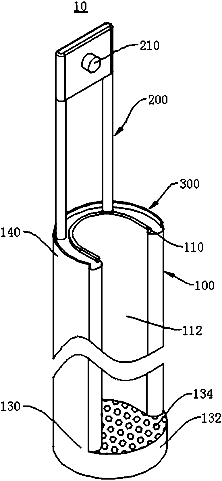
[0041] Please refer to Figure 1 to Figure 4 , the present embodiment provides an engine oil dipstick 10, which includes a ruler body 100; the ruler body 100 is provided with a groove, and the inner wall of the groove is provided with a magnetic part 110 for magnetically sucking the iron inside the oil; the magnetic part 110 is provided with a useful In the accommodating space 112 for accommodating iron cutting; along the length direction of the ruler body 100 is also provided with a scale line 120 .

[0042]The engine oil dipstick 10 provided in the embodiment of the present invention includes a ruler body 100; the ruler body 100 is provided with a groove, and the inner wall of the groove is provided with a magnetic part 110 for iron cutting in the magnetic suction machine oil; the magnetic part 110 is provided with There is an accommodating space 112 for accommodating iron cutting; a scale line 120 is also provided along the length direction of the ruler body 100, a groove i...

Embodiment 2

[0059] An oil pan is also provided in this embodiment, and the oil pan includes the above-mentioned engine oil dipstick 10 and the oil pan body; The engine oil dipstick 10 is used to extend into or out of the accommodating cavity.

[0060] The oil pan provided in the embodiment of the present invention includes the above-mentioned engine oil dipstick 10, so it can also avoid the problem that the outer wall of the ruler body 100 is difficult to protrude out of the oil pan due to the increase of the outer diameter of the outer wall of the ruler body 100 due to magnetic iron filings. The oil dipstick hole prevents the iron filings adsorbed on the outer peripheral wall of the ruler body 100 from being scraped off when it stretches out from the oil dipstick hole of the oil pan, and falls back into the engine oil again, causing problems such as clogging the filter.


PUM


Abstract

The invention discloses an engine oil dip stick and an oil pan, and relates to the technical field of engines. According to the engine oil dip stick provided by the invention, when the engine oil dipstick is stretched into the oil pan to measure the oil quantity, iron scraps mixed in engine oil are adsorbed in an accommodating space of a magnetic part due to attractive force of the magnetic part,and the problems that the outer diameter of the outer wall of a stick body is increased and the stick body is hardly stretched into a dip stick hole of the oil pan due to the fact that the outer wallof the stick body magnetically adsorbs the iron scraps, the iron scraps adsorbed on the peripheral wall of the stick body are scraped and fall into engine oil again when the dip stick is stretched out of the dip stick hole of the oil pan, and a filter is blocked are solved. The oil pan provided by the invention comprises the engine oil dip stick and has the beneficial effects.

Description

technical field [0001] The invention relates to the technical field of engines, in particular to an engine oil dipstick and an oil pan. Background technique [0002] During the operation of the engine, due to friction and wear, it is inevitable to produce a large amount of iron filings, and most of them are mixed into the engine oil. If these iron filings are not separated from the engine oil, and continue to be re-delivered to various lubricating parts with the circulation of the engine oil, then not only will the lubrication effect not be achieved, but the wear of the machine will be accelerated. At present, in addition to filtering and separating iron filings with filters, people also use the method of adding magnetic materials to some parts to magnetically attract and separate iron filings in advance to achieve the purpose of purifying the engine oil. [0003] The oil dipstick is originally inserted into the engine oil in the crankcase (also known as the oil pan) of the...

Claims


Application Information

Patent Timeline
IPC IPC(8): F01M11/12F01M11/00F01M11/03
CPCF01M11/0004F01M11/03F01M11/12
Inventor 白云龙
Owner SHAANXI JUZHEN POWER TECH CO LTD
Learn More