

Sole frictional wear testing device and system
A testing device, a technology of friction and wear, applied in the measurement device of feet or shoe lasts, testing wear resistance, footwear, etc., can solve problems such as high price, difference in wear resistance of soles, single test device, etc., and achieve a working cycle Long, compact and cheap effect
- Summary
- Abstract
- Description
- Claims
- Application Information
AI Technical Summary
Problems solved by technology
Method used
Image

Examples
no. 1 example
[0100] First embodiment: measure the relationship between the number of times the same shoe is walked on rough ground and the wear degree of the sole.
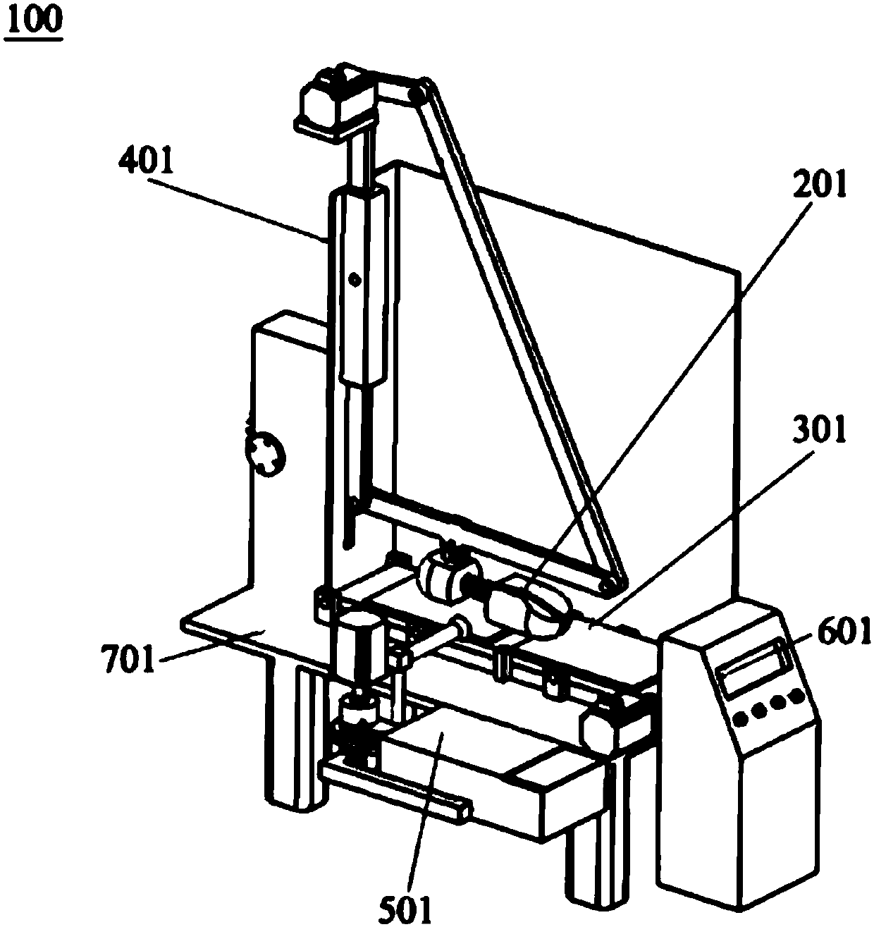
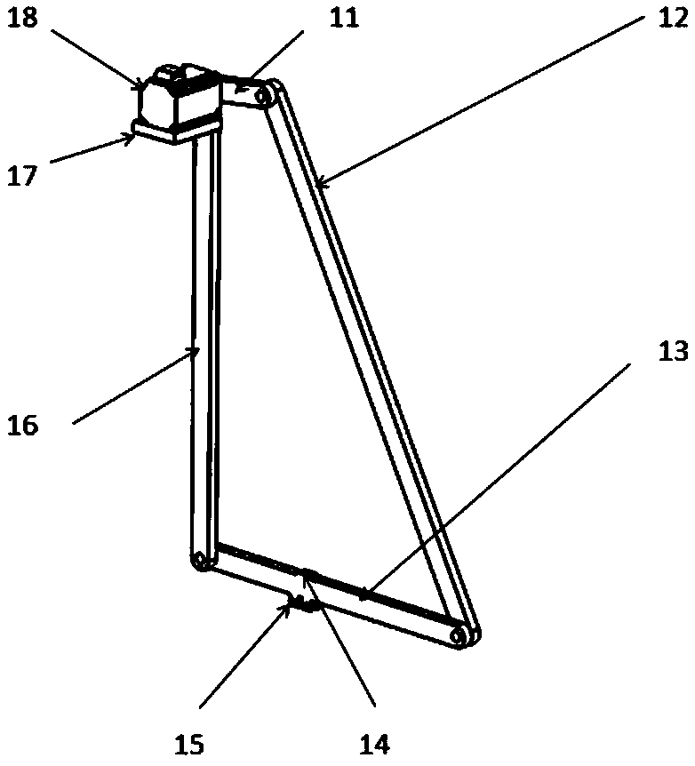
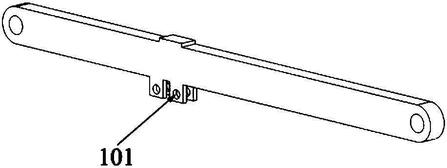
[0101]The operator inserts the head of the shoe last 202 into the shoe, and uses the rebound force of the spring to make the front end of the shoe last 202 press against the shoe cavity to fill the toe. With a little force, the spring connecting rod between the toe and the heel 21 The expansion and contraction of the backstay makes the back of the shoe tight, and finally the shoe last 202 is pressed into the shoe and the shoelaces are fastened, and the fixed end of the shoe last 202 (set at the heel 21 of the fixing member 201) passes through the fixing hole The (first hole) position is fixed on the 300mm connecting rod, and the angle of the shoes to the ground is adjusted through the relative position of the fixed end of the shoe last 202 and the fixed hole position. After the power switch 72 of the electric console is presse...
no. 2 example
[0102] Second embodiment: comparing the anti-skid ability of different shoes on slippery ground under the same wear condition
[0103] The operator inserts the head of the shoe last 202 into the shoe, and uses the rebound force of the spring to make the front end of the shoe last 202 press against the shoe cavity to fill the toe. With a little force, the spring connecting rod between the toe and the heel 21 The expansion and contraction of the backstay makes the back of the shoe tight, and finally press the shoe last 202 into the shoe and fasten the shoelaces, fix the fixed end of the shoe last 202 on the 300mm connecting rod through the fixing hole, and pass the shoe last 202 The relative position of the fixed end and the fixed hole adjusts the angle of the shoes to the ground. After the power switch 72 of the electric console is pressed, the handwheel on the lifting table 54 is rotated, and the longitudinal movement of the gear 55 and the rack 56 is used to drive the up and ...
no. 3 example
[0104] Embodiment 3: Judging the frictional force of the same shoe when walking on a rainy road after a certain degree of wear on a rough ground.
[0105] The operator inserts the head of the shoe last 202 into the shoe, and uses the rebound force of the spring to make the front end of the shoe last 202 press against the shoe cavity to fill the toe. With a little force, the spring connecting rod between the toe and the heel 21 The expansion and contraction of the backstay makes the back of the shoe tight, and finally press the shoe last 202 into the shoe and fasten the shoelaces, fix the fixed end of the shoe last 202 on the 300mm connecting rod through the fixing hole, and pass the shoe last 202 The relative position of the fixed end and the fixed hole adjusts the angle of the shoes to the ground. After the power switch 72 of the electric console is pressed, the handwheel on the lifting table 54 is rotated, and the longitudinal movement of the gear 55 and the rack 56 is used ...
PUM
 Abstract
Description
Claims
Application Information