Spiral falling-film evaporator

A falling-film evaporator and spiral technology, applied in the field of spiral falling-film evaporators, can solve the problems of reduced evaporation efficiency of falling-film evaporators, slowed down flow rate of annular liquid film, and reduced heat transfer efficiency of annular liquid film, etc. To achieve the effect of improving convective heat transfer efficiency, improving evaporation concentration efficiency, and improving heat transfer efficiency

Pending Publication Date: 2018-03-23
江苏迈克化工机械有限公司
View PDF6 Cites 4 Cited by
  • Summary
  • Abstract
  • Description
  • Claims
  • Application Information

AI Technical Summary

Problems solved by technology

[0002] In the evaporation industry, there is a falling film evaporator that can evaporate and concentrate the solution, such as figure 1 The common falling film evaporator shown includes upper cylinder body 1, evaporating raw liquid inlet 2, falling film tube 3, upper tube plate 4, shell 5, heating steam inlet 6, condensed water outlet 7, lower tube plate 8, evaporation The original liquid enters the upper cylinder 1 from the evaporation original liquid inlet 2, and the heating steam enters the shell 5 from the heating steam inlet 6. When the liquid level of the evaporated original liquid in the upper cylinder 1 rises to the upper tube of the falling film tube 3 When the mouth is opened, the film will be distributed from the entire upper nozzle to the inside of the tube, and a uniform liquid film will be formed on the inner wall of the falling film tube 3 and flow downward under the action of gravity. 5. The heating of the steam in the interior makes the temperature of the liquid film rise, reach the boiling point, and cause evaporation. The secondary steam generated by evaporation breaks away from the surface of the liquid film and enters the center of the falling film tube 3, and drives the liquid film on the inner wall of the falling film tube 3 downward together. flow, after the evaporation and concentration are completed, the concentrated liquid and the secondary steam flow out from the lower port of the falling film tube 3 together, and the generated new steam condensate flows out from the condensed water outlet 7. The falling film tube 3 in this device is a common round tube. The annular liquid film formed on the inner wall of the falling film tube 3 and the secondary steam at the center of the annular liquid film all flow vertically downward. Due to the viscosity of the evaporating solution and the roughness of the inner wall of the falling film tube 3, the circular liquid film descends at a velocity slow down, the convective heat transfer efficiency of the circular liquid film is reduced, resulting in a reduction in the evaporation efficiency of the falling film evaporator

Method used


Image

  • Spiral falling-film evaporator
  • Spiral falling-film evaporator
  • Spiral falling-film evaporator

Examples


Embodiment Construction

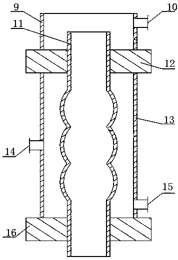
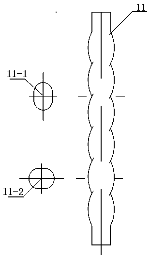
[0011] The evaporated raw liquid enters the upper cylinder 9 from the evaporation raw liquid inlet 10, and the heating steam enters the shell 13 from the heated steam inlet 14. When the liquid level of the evaporated raw liquid in the upper cylinder 9 rises to the upper tube of the spiral falling film tube 11 When the mouth is opened, the film will be distributed from the upper nozzle to the inside of the tube, and a uniform annular liquid film will be formed on the inner wall of the spiral falling film tube 11. When the annular liquid film flows downward under the action of gravity, it will flow along the spiral falling film. The spiral channel formed by the inner wall of the tube 11 changes the speed and direction periodically, so that the evaporated solution is always in a turbulent state; in the spiral falling film evaporator, the annular liquid film quickly absorbs the shell during the downward flow. The thermal energy of the steam in 13 raises the temperature of the liqui...


PUM


Abstract

The invention provides a spiral falling-film evaporator, and belongs to the field of chemical industry production. The spiral falling-film evaporator comprises an upper barrel, an evaporated stock solution inlet, a spiral falling-film tube, an upper tube plate, a shell, a heating steam inlet, a condensed water outlet and a lower tube plate. The upper end of the upper tube plate is connected with the upper barrel, the evaporated stock solution inlet is formed in the upper end of a side surface of the upper barrel, the lower end of the upper tube plate is connected with the shell, the heating steam inlet is formed in the middle of a side surface of the shell, the condensed water outlet is formed in the bottom of a side surface of the shell, the lower end of the shell is connected with the lower tube plate, the spiral falling-film tube is arranged between the upper tube plate and the lower tube plate, an upper orifice of the spiral falling-film tube extends out of the upper portion of theupper tube plate and is close to the evaporated stock solution inlet, and a lower orifice of the spiral falling-film tube extends out of the lower portion of the lower tube plate. The spiral falling-film evaporator has the advantage that the evaporation concentration efficiency of the spiral falling-film evaporator can be improved.

Description

technical field [0001] The invention belongs to the field of chemical production, in particular to a spiral falling film evaporator. Background technique [0002] In the evaporation industry, there is a falling film evaporator that can evaporate and concentrate the solution, such as figure 1 The common falling film evaporator shown includes upper cylinder body 1, evaporating raw liquid inlet 2, falling film tube 3, upper tube plate 4, shell 5, heating steam inlet 6, condensed water outlet 7, lower tube plate 8, evaporation The original liquid enters the upper cylinder 1 from the evaporation original liquid inlet 2, and the heating steam enters the shell 5 from the heating steam inlet 6. When the liquid level of the evaporated original liquid in the upper cylinder 1 rises to the upper tube of the falling film tube 3 When the mouth is opened, the film will be distributed from the entire upper nozzle to the inside of the tube, and a uniform liquid film will be formed on the in...

Claims


Application Information

Patent Timeline
Patent Type & Authority Applications(China)
IPC IPC(8): B01D1/22
CPCB01D1/22
Inventor 曾锡华杜修权彭小红
Owner 江苏迈克化工机械有限公司
Why Eureka
Try Eureka