Sifter

A technology of screening machine and wood fiber board, which is applied in the direction of solid separation, separation of solids from solids by air flow, pretreatment of molding materials, etc., can solve problems such as unfavorable screening, and achieve the goal of improving screening quality and increasing capacity Effect

Inactive Publication Date: 2018-03-23
SIEMPELKAMP MASCH & ANLAGENBAU GMBH & CO KG
View PDF11 Cites 2 Cited by
  • Summary
  • Abstract
  • Description
  • Claims
  • Application Information

AI Technical Summary

Problems solved by technology

Although a greater amount of material can be picked up by the air stream by increasing the velocity of the incoming air, this is not conducive to sieving

Method used


Image

  • Sifter
  • Sifter
  • Sifter

Examples


Embodiment Construction

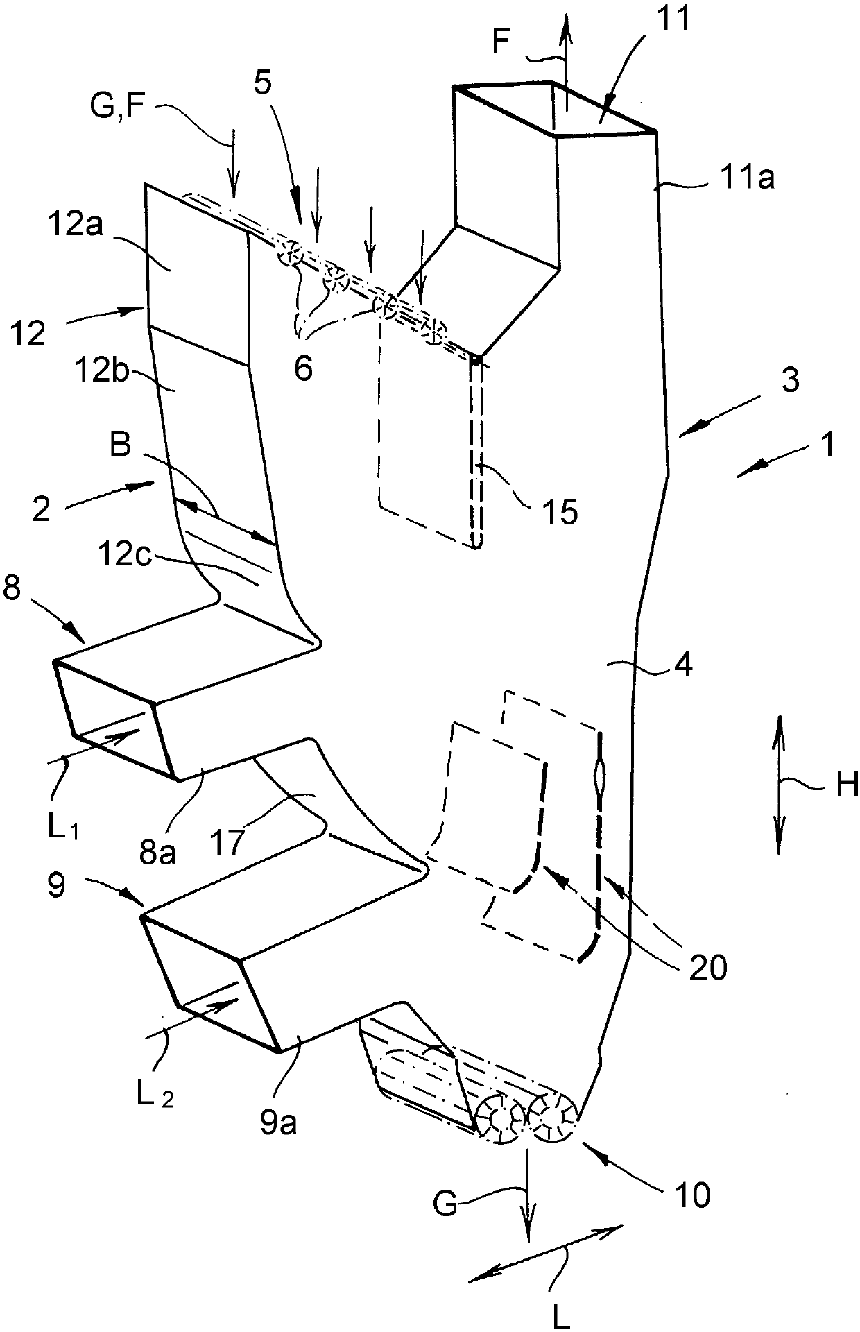
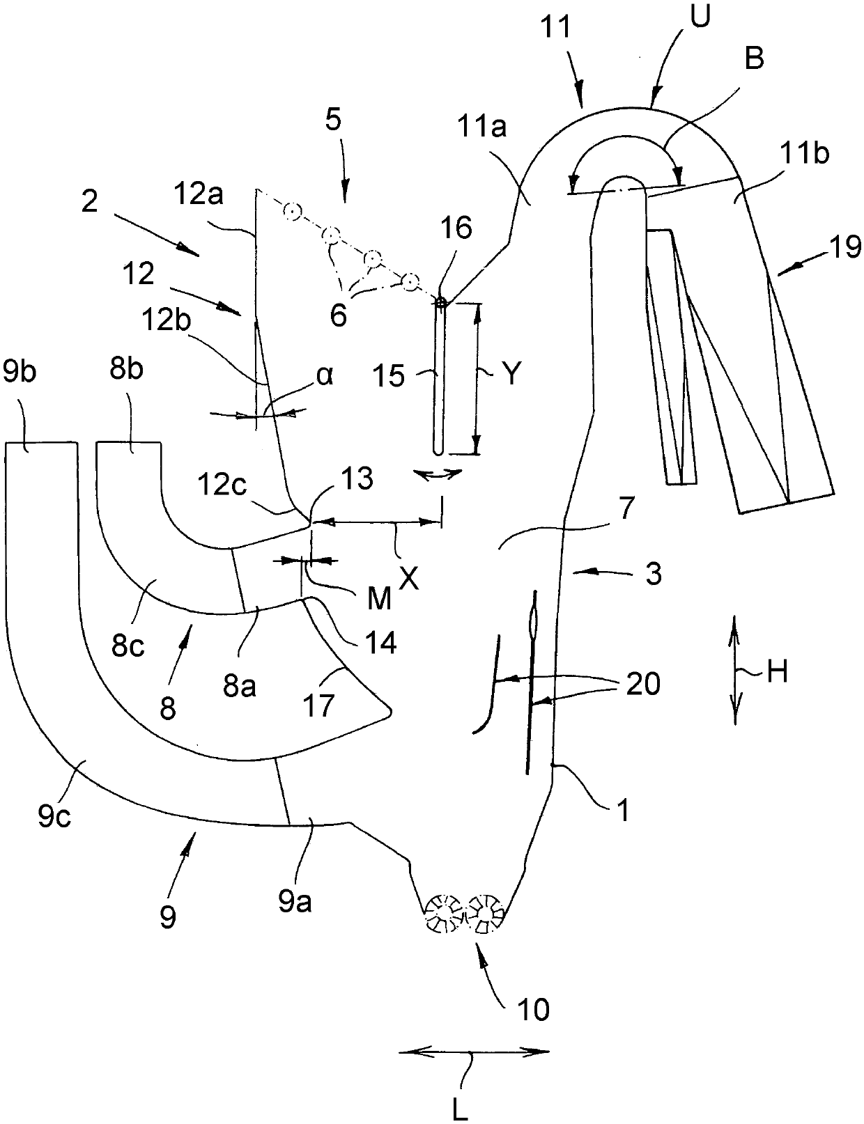
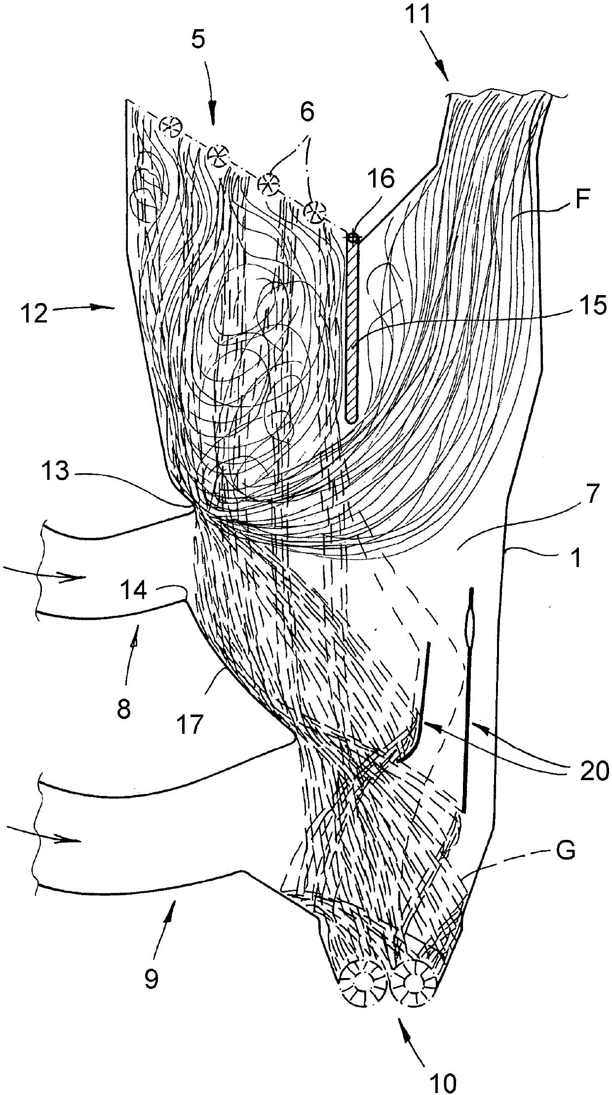
[0023] The drawing shows a sieving machine for separating coarse particles from a particle flow, especially a fiber flow, during the production of wood-based boards, especially wood-fibre boards. Such a sieving machine is preferably integrated in a plant for the production of wood-based material boards, in particular in order to remove undesired components (such as metal parts, adhesive clumps, coarse fibers, rust flakes or the like) from the material flow (such as glued fibers) objects), more precisely in particular in order to protect downstream equipment or equipment components (such as the steel belt of a continuously operating wood-based material panel press) from damage.

[0024] The screening machine has a screening machine housing 1 which in its basic structure comprises a front wall 2 , a rear wall 3 and two side walls 4 . The designations “front wall 2 ” and “rear wall 3 ” refer here to the main flow direction of the incoming sieving air. The screen housing 1 has on...


PUM


Abstract

The invention relates to a sifter serves for separating coarse particles from a particle-carrying stream during the manufacture of wood material panels, in particular wood fiber panels. The sifter comprises at least one sifter housing having a feed inlet, at least one air inlet, an air outlet, and a coarse feed outlet disposed below the feed inlet. The upper front wall of the screen housing, whichis arranged above the air inlet, is oriented obliquely with respect to the vertical line at least in partial regions. The screening machine is characterized in that the upper edge of the air inlet isaligned in side view above the lower edge of the air inlet or protrudes by an amount (M) from the lower edge.

Description

technical field [0001] The invention relates to a screening machine for separating coarse particles from a particle flow during the manufacture of wood material boards, especially wood fiber boards, comprising at least one screening machine housing with further A feed port, at least one air inlet arranged below the feed inlet, an exhaust port (arranged above the air inlet) and a coarse material outlet (arranged below the air inlet), the screening machine housing is arranged at The upper front wall above the air inlet is oriented obliquely to the vertical at least in partial regions, ie over a certain height section. Background technique [0002] Sifters of this type are used in the wood industry for cleaning particle streams and in particular for screening out unwanted components from the particle stream. For example, metal parts, coarse fibers, rust flakes, adhesive particles or adhesive clumps should be removed in order to protect downstream equipment or equipment parts, ...

Claims


Application Information

Patent Timeline
Patent Type & Authority Applications(China)
IPC IPC(8): B07B4/02B07B11/02B27N1/00
CPCB07B7/083B07B4/02B07B11/02B27N1/00B07B11/04B27N3/18B07B7/04B07B11/06
Inventor L·科洛瑟S·克纳伯E·塞弗勒
Owner SIEMPELKAMP MASCH & ANLAGENBAU GMBH & CO KG
Why Eureka
Try Eureka