Steel pipe cutting device for engineering material

A cutting device and engineering material technology, applied in the direction of pipe shearing device, shearing device, attachment device of shearing machine, etc., can solve the problems of inability to adjust the cutting angle, easy injury in the cutting process, time-consuming and labor-intensive, etc. Effect

Inactive Publication Date: 2018-03-23
刘世荣
View PDF4 Cites 9 Cited by
  • Summary
  • Abstract
  • Description
  • Claims
  • Application Information

AI Technical Summary

Problems solved by technology

[0005] In order to overcome the time-consuming and labor-intensive cutting process of the steel pipe, the present invention is easy to be injured during the cutting process, and the existing cutting device is complicated to operate and cannot adjust the cutting angle. The technical problem to be solved by the present invention is to provide a A steel pipe cutting device for engineering materials that saves time and effort, does not cause injury during cutting, is easy to operate, and can adjust the cutting angle

Method used


Image

  • Steel pipe cutting device for engineering material
  • Steel pipe cutting device for engineering material
  • Steel pipe cutting device for engineering material

Examples


Embodiment 1

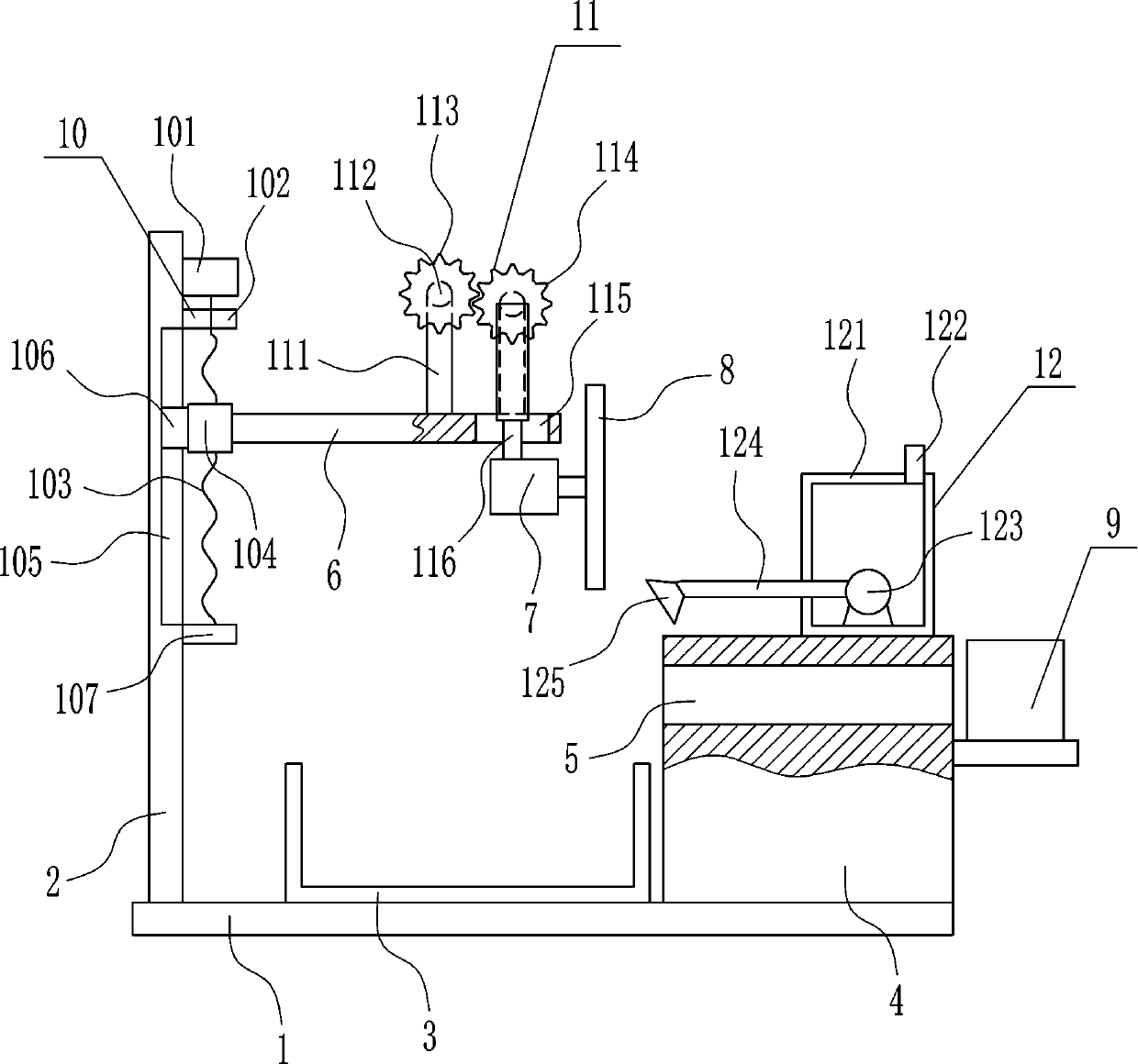
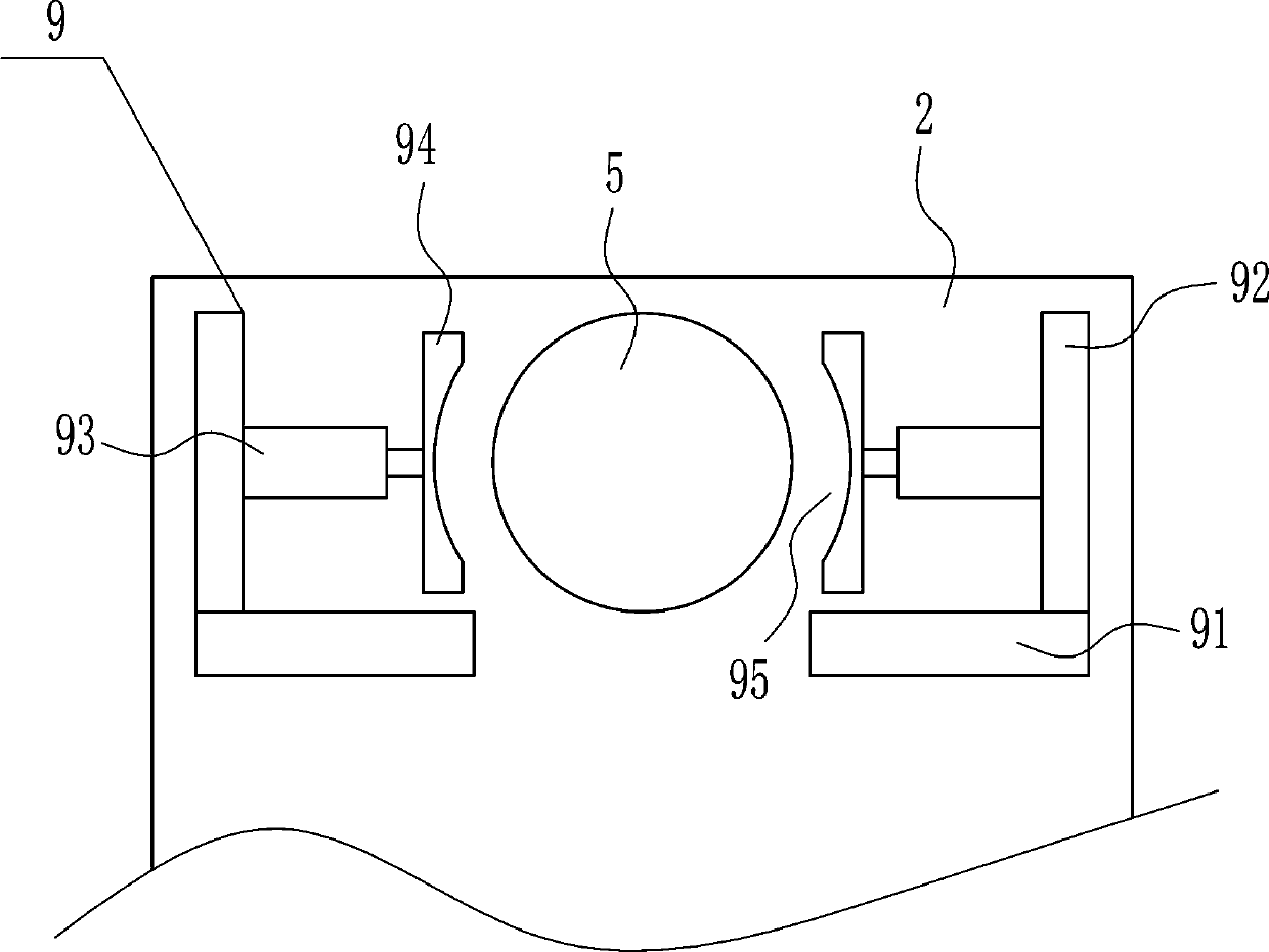
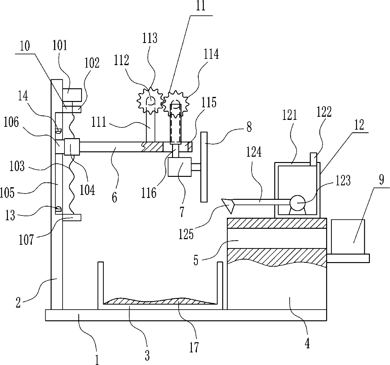
[0037] A steel pipe cutting device for engineering materials, such as Figure 1-7 As shown, it includes a base plate 1, a support plate 2, a collection frame 3, a fixed seat 4, a horizontal plate 6, a first motor 7, a cutting knife 8, a fixing device 9 and a moving device 10, and the top of the base plate 1 passes through from left to right The support plate 2, the collection frame 3 and the fixing seat 4 are installed in the way of bolt connection, the upper part of the fixing seat 4 has a placement hole 5, and the upper part of the right side of the fixing seat 4 is provided with a fixing device 9, and the fixing device 9 is located on the right side of the placement hole 5 A moving device 10 is arranged on the upper right side of the support plate 2, and a horizontal plate 6 is connected to the moving part of the moving device 10, and a first motor 7 is installed on the right side of the bottom of the horizontal plate 6 through bolt connection, and the first motor 7 is Hori...

Embodiment 2

[0039] A steel pipe cutting device for engineering materials, such as Figure 1-7 As shown, it includes a base plate 1, a support plate 2, a collection frame 3, a fixed seat 4, a horizontal plate 6, a first motor 7, a cutting knife 8, a fixing device 9 and a moving device 10, and the top of the base plate 1 passes through from left to right The support plate 2, the collection frame 3 and the fixing seat 4 are installed in the way of bolt connection, the upper part of the fixing seat 4 has a placement hole 5, and the upper part of the right side of the fixing seat 4 is provided with a fixing device 9, and the fixing device 9 is located on the right side of the placement hole 5 A moving device 10 is arranged on the upper right side of the support plate 2, and a horizontal plate 6 is connected to the moving part of the moving device 10, and a first motor 7 is installed on the right side of the bottom of the horizontal plate 6 through bolt connection, and the first motor 7 is Hori...

Embodiment 3

[0042] A steel pipe cutting device for engineering materials, such as Figure 1-7 As shown, it includes a base plate 1, a support plate 2, a collection frame 3, a fixed seat 4, a horizontal plate 6, a first motor 7, a cutting knife 8, a fixing device 9 and a moving device 10, and the top of the base plate 1 passes through from left to right The support plate 2, the collection frame 3 and the fixing seat 4 are installed in the way of bolt connection, the upper part of the fixing seat 4 has a placement hole 5, and the upper part of the right side of the fixing seat 4 is provided with a fixing device 9, and the fixing device 9 is located on the right side of the placement hole 5 A moving device 10 is arranged on the upper right side of the support plate 2, and a horizontal plate 6 is connected to the moving part of the moving device 10, and a first motor 7 is installed on the right side of the bottom of the horizontal plate 6 through bolt connection, and the first motor 7 is Hori...


PUM


Abstract

The invention relates to a cutting device, in particular to a steel pipe cutting device for an engineering material. According to the technical purposes of the steel pipe cutting device for the engineering material, time and labor are saved, a user is not injured in the cutting process, operation is easy, and the cutting angle can also be adjusted. In order to achieve the technical purposes, the steel pipe cutting device for the engineering material comprises a bottom plate and the like; a supporting plate, a collecting frame and a fixed base are sequentially installed on the top of the bottomplate from left to right in a bolt connection manner; the upper portion of the fixed base is provided with a containing hole; and a fixed device is arranged on the upper portion of the right side face of the fixed base, and is located on the right side of the containing hole. According to the steel pipe cutting device for the engineering material, by adjusting the cutting angle, a steel bar can be cut to a needed angle, water is sprayed onto a cutter, the cutter can be cooled, the service life is longer, and the effects that time and labor are saved, the user is not injured in the cutting process, operation is easy, and the cutting angle can also be adjusted are achieved.

Description

technical field [0001] The invention relates to a cutting device, in particular to a steel pipe cutting device for engineering materials. Background technique [0002] Engineering materials: materials used in engineering fields such as machinery, vehicles, ships, construction, chemicals, energy, instrumentation, aerospace, etc. It is used to manufacture engineering components and mechanical parts, and also includes some materials used to manufacture tools and materials with special properties. [0003] In engineering construction, the use of steel pipes is very common. Before the steel pipes are used, the steel pipes will be cut to reach the required length. When cutting the steel pipes manually, it is time-consuming and labor-intensive, and it is easy to be injured during the cutting process. However, the existing cutting In the device, the operation is complicated and the cutting angle cannot be adjusted. Therefore, it is urgent to develop a steel pipe cutting device for ...

Claims


Application Information

Patent Timeline
Patent Type & Authority Applications(China)
IPC IPC(8): B23D21/00B23Q11/10B23Q1/25B23D33/02
CPCB23D21/00B23D33/02B23Q1/25B23Q11/10
Inventor 邓文雅李芳李叶鑫其他发明人请求不公开姓名
Owner 刘世荣
Why Eureka
Try Eureka