
Long-short-pile composite foundation applied to deep soft soil regions

A technology of composite foundation and long and short piles, which is applied in the direction of foundation structure engineering, construction, etc., can solve the problems of small horizontal constraint force, uneven load sharing, and large settlement, so as to avoid displacement or damage of pile body and pile foundation Quality is safe and reliable, quality is safe and reliable effect

Inactive Publication Date: 2018-03-23
CHINA MCC17 GRP
View PDF4 Cites 2 Cited by
  • Summary
  • Abstract
  • Description
  • Claims
  • Application Information

AI Technical Summary

Problems solved by technology

(1) Pure long pile foundation is used for deep soft soil. Due to the large length-to-diameter ratio of the pile and the low horizontal restraint of the pile by the muddy pile surrounding soil, the stability of the pile is poor and it is easy to inclination of the pile
(2) Pure short piles are used for foundation treatment of deep soft soil, and the settlement of piles is relatively large. If soil-squeezing piles are used, due to the low bearing capacity of single piles and the large coefficient of plane pile layout, they will be damaged in saturated muddy soil. A large soil squeezing effect is produced, which makes it difficult to guarantee the quality of the project; if non-squeezing piles are used, the cost is not low due to the large number of piles, and the construction speed is slow and the construction period is long
(3) Traditional long-short piles include rigid-flexible composite piles and rigid composite piles. The pipe piles of the two types of long-short pile combinations are rigidly connected to the foundation cap. The entire system is only a pile foundation form, which is likely to cause stress concentration The pipe piles rigidly connected to the foundation cap, the short piles have a small load-bearing effect and cannot evenly share the load

Method used


Image

  • Long-short-pile composite foundation applied to deep soft soil regions
  • Long-short-pile composite foundation applied to deep soft soil regions

Examples


Embodiment Construction

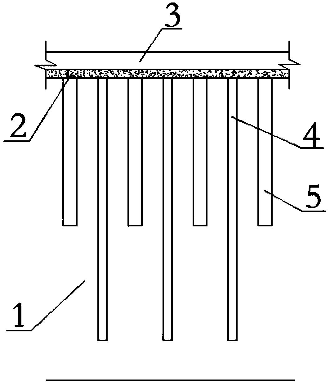
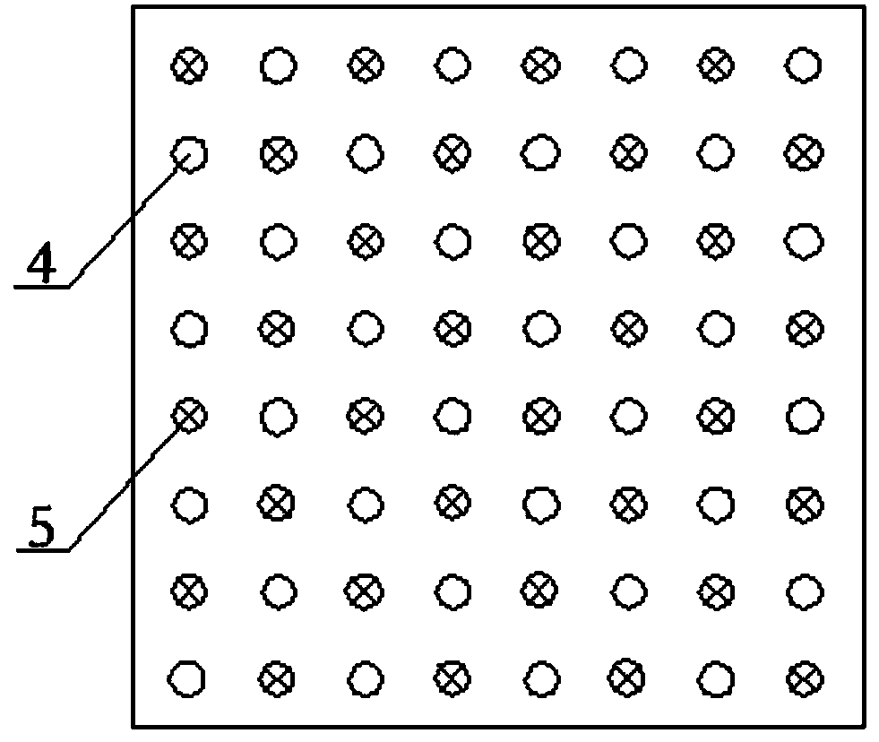
[0014] The present invention will be described in further detail below in conjunction with accompanying drawing, so that those skilled in the art can understand more clearly, as figure 1 and figure 2 Shown, the present invention adopts following embodiment, comprises weak soil layer 1, mattress layer 2, foundation 3, long pile 4 and short pile 5; Described mattress layer 2 is positioned on weak soil layer 1, and described foundation 3 is positioned at On the cushion layer 2; the cushion layer may be able to adjust the load sharing ratio of the pile and the soil between the piles and the load sharing ratio of the long pile and the short pile. Described long pile 4 and short pile 5 are arranged in the soft soil layer 1; Located in the soft soil layer 1; the long piles 4 are evenly and symmetrically located around the short piles 5, and the short piles 5 are evenly and symmetrically located around the long piles 4; It can evenly bear the load and further reduce the settlement;...


PUM


Abstract

The invention discloses a long-short-pile composite foundation applied to deep soft soil regions. The long-short-pile composite foundation comprises a soft soil layer, a cushion layer, a base, long piles and short piles, wherein the cushion layer is located above the soft soil layer; the base is located above the cushion layer; the long piles and the short piles are arranged in the soft soil layer; the pile tops of the long piles and the short piles are in contact with the bottom surface of the cushion layer; the pile toes of the long piles and the short piles are located in the soft soil layer; the long piles are uniformly and symmetrically located around the short piles; the short piles are uniformly and symmetrically located around the long piles. The long-short-pile composite foundation applied to deep soft soil regions is capable of uniformly sharing the upper load and preventing stress concentration, is simple and stable in structure, convenient to construct and safe and reliablein quality, and is capable of effectively controlling settlement deformation.

Description

technical field [0001] The invention relates to the field of construction, in particular to foundation treatment of deep soft soil, in particular to a composite foundation of long and short piles in deep soft soil areas. Background technique [0002] Deep and thick soft soil layers have the characteristics of high compressibility, low strength, high sensitivity, low water permeability, large void ratio, and high natural water content. Traditional foundation treatment methods have many defects. (1) Pure long pile foundation is used for deep soft soil. Due to the large length-to-diameter ratio of the pile and the low horizontal restraint of the pile by the muddy pile surrounding soil, the stability of the pile is poor and it is easy to The pile body tilts. (2) Pure short piles are used for foundation treatment of deep soft soil, and the settlement of piles is relatively large. If soil-squeezing piles are used, due to the low bearing capacity of single piles and the large coef...

Claims


Application Information

Patent Timeline
Patent Type & Authority Applications(China)
IPC IPC(8): E02D27/16
CPCE02D27/16
Inventor 徐正中桂光红
Owner CHINA MCC17 GRP
Learn More