
Building construction equipment capable of automatically constructing coping of masonry wall of floor house

A technology for building construction and housing, applied in the field of roofing construction equipment for building floors and buildings, can solve the problems of high labor intensity, potential safety hazards, uneven vibration, etc., and achieve the effects of reducing labor volume, improving work efficiency, and reducing working hours.

Inactive Publication Date: 2018-03-23
吴秋敏
View PDF0 Cites 7 Cited by
  • Summary
  • Abstract
  • Description
  • Claims
  • Application Information

AI Technical Summary

Problems solved by technology

[0003] In order to make up for the deficiencies in the prior art, the present invention provides a building construction equipment that can be automatically constructed for building masonry walls for roofing, which can solve the problems of high labor intensity, low work efficiency, and vibration in the existing wall roofing construction process. Uneven solidity, large potential safety hazards, and easy inclusion of impurities in the concrete conveying process can realize the function of automatic roofing construction, which has the advantages of low labor intensity, high work efficiency, uniform vibration, no safety hazards, and no impurities.

Method used


Image

  • Building construction equipment capable of automatically constructing coping of masonry wall of floor house
  • Building construction equipment capable of automatically constructing coping of masonry wall of floor house
  • Building construction equipment capable of automatically constructing coping of masonry wall of floor house

Examples


Embodiment Construction

[0027] In order to make the technical means, creative features, goals and effects achieved by the present invention easy to understand, the present invention will be further described below in conjunction with specific illustrations.

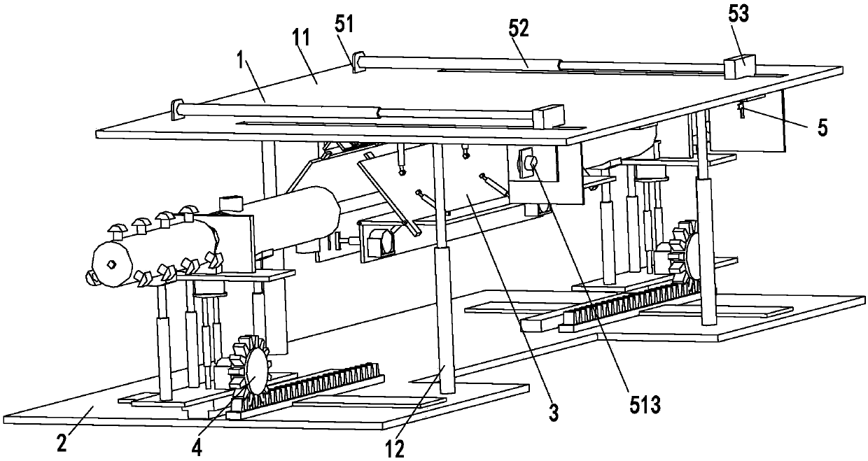
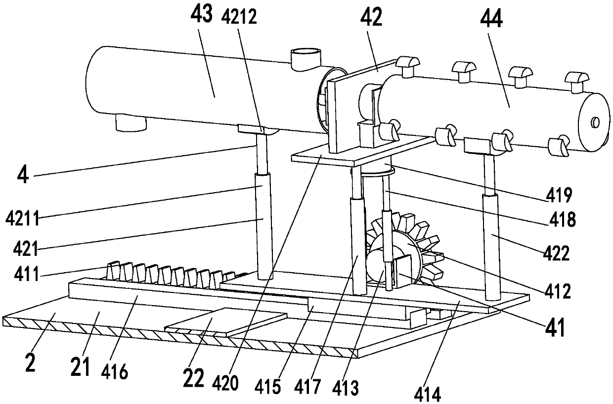
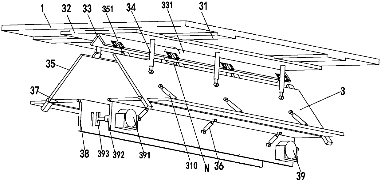
[0028] Such as Figure 1 to Figure 6 As shown, a kind of building construction equipment that can be automatically constructed by building masonry walls and roofing, including a mounting frame 1, a bottom plate 2, a formwork support device 3, a concrete pouring device 4 and an extrusion device 5, and the mounting frame 1 is installed on On the bottom plate 2, a template support device 3 is installed at the lower end of the mounting frame 1, and an extrusion device 5 is installed at the upper end of the mounting frame 1. The number of extrusion devices 5 is two, and the two extrusion devices 5 are symmetrically installed at the left and right ends of the mounting frame 1. Concrete pouring devices 4 are installed on the bottom plate 2, the number ...


PUM


Abstract

The invention relates to a kind of building construction equipment that can be automatically constructed by masonry wall pressing of a storey house. It includes a mounting frame, a bottom plate, a formwork support device, a concrete pouring device and an extrusion device. A formwork support device is installed, and an extrusion device is installed on the upper end of the installation frame. The number of extrusion devices is two. The two extrusion devices are symmetrically installed at the left and right ends of the installation frame. A concrete pouring device is installed on the bottom plate. The number of concrete pouring devices is two. , two concrete pouring devices are installed symmetrically at the left and right ends of the bottom plate. The invention can solve the problems of high labor intensity, low work efficiency, uneven compaction, large safety hazards and easy mixing of impurities in the process of concrete conveying existing in the existing wall construction process, and can realize the function of automatic construction of the top. It has the advantages of low labor intensity, high work efficiency, uniform vibration, no safety hazard and no impurity mixing.

Description

technical field [0001] The invention relates to the field of roofing construction equipment for building floors and houses, in particular to a building construction equipment that can be automatically constructed for roofing the walls of floors and houses. Background technique [0002] Top pressure refers to the 50 to 100mm thick concrete structure poured on the top of the masonry wall of the building floor (if there is no other structure above), to press the top of the wall to prevent the top blocks (such as bricks) from being weathered or shaken by the masonry mortar (such as wind or earthquake), collided and loosened and dropped. On the top of the gravity slab or the top of the mortar block stone flood control wall, cast a piece of strip (reinforced steel) concrete as top pressure, and its function is to enhance the structural integrity. The top of the open-air wall is covered with bricks, tiles, stones, concrete, reinforced concrete, galvanized iron sheets, etc., the mo...

Claims


Application Information

Patent Timeline
Patent Type & Authority Applications(China)
IPC IPC(8): E04G21/04E04G21/06
CPCE04G21/04E04G21/066
Inventor 吴秋敏
Owner 吴秋敏
Learn More