Pile foundation type test well building method

A pile foundation and wellbore technology, which is applied in the direction of sinking, shaft equipment, mining equipment, etc., can solve the problems of long construction period, inconvenient maintenance, and large investment of test wells, and achieve reduced construction costs, land saving, and low operating costs Effect

Active Publication Date: 2018-03-23
PETROCHINA CO LTD
View PDF6 Cites 0 Cited by
  • Summary
  • Abstract
  • Description
  • Claims
  • Application Information

AI Technical Summary

Problems solved by technology

[0003] In order to solve the problem that the existing test wells built above the ground have a long construction period, the invention provides a construction method for pile-based test wells, which solves the problem that the existing test wells have a long construction period. Large investment and inconvenient maintenance

Method used


Image

  • Pile foundation type test well building method
  • Pile foundation type test well building method
  • Pile foundation type test well building method

Examples


Embodiment 1

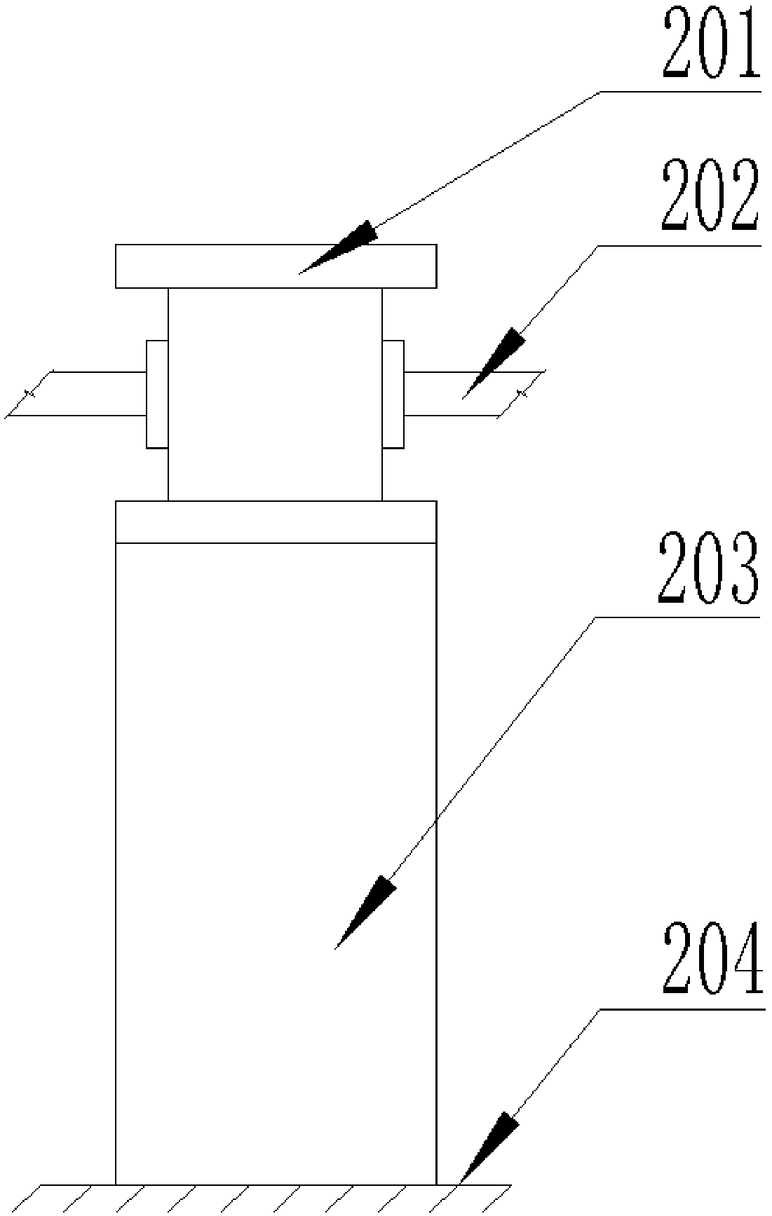
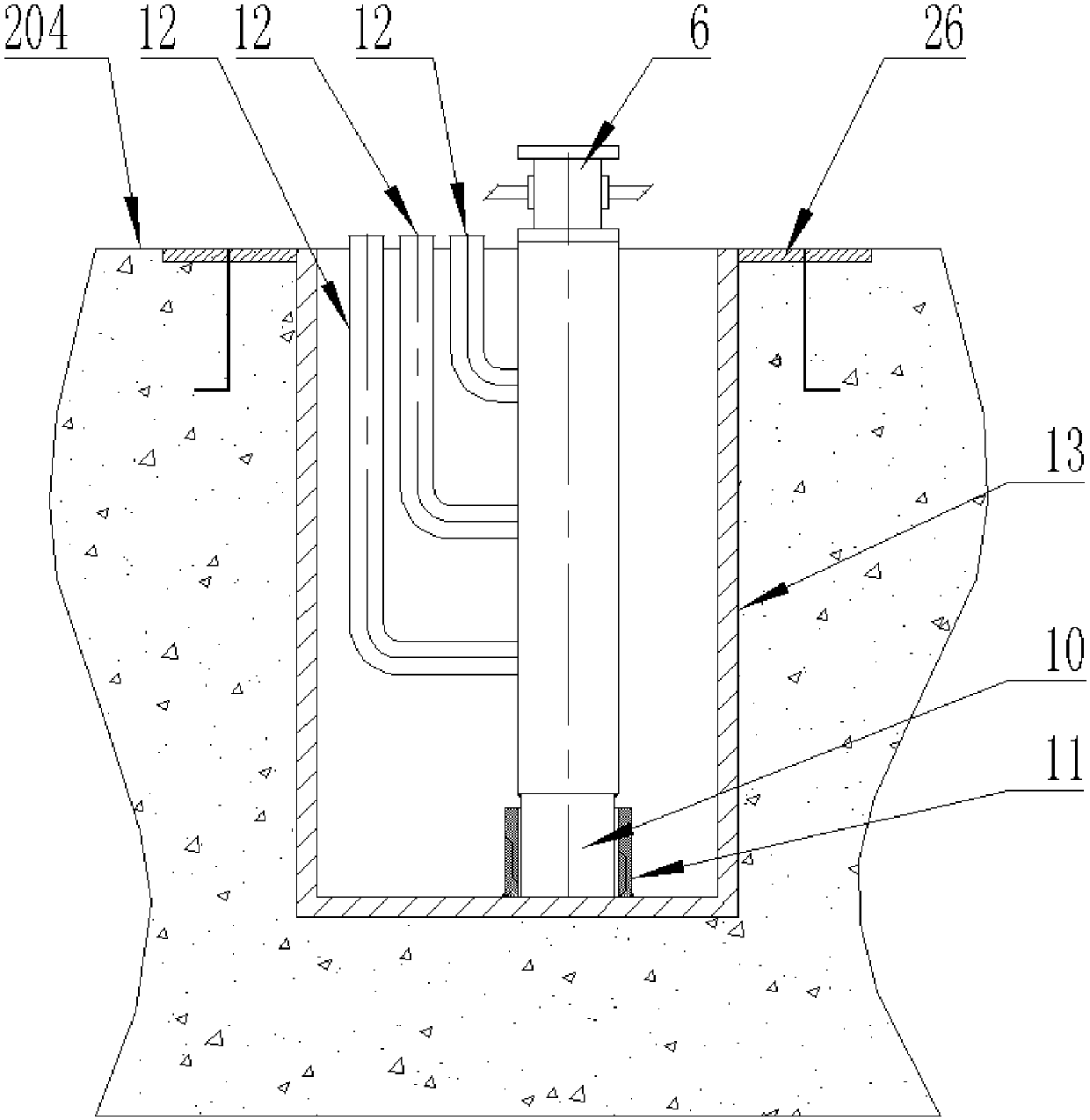
[0048] In this embodiment, the pile-based test well may be a vertical normal temperature test well, and the suitable operating temperature range is 25°C to 120°C. The test outer wellbore contains a support 14 connected up and down and an outer casing 13. The outer diameter of the outer casing 13 matches the diameter of the wellbore. The outer diameter of the outer casing 13 is 660mm, and the depth of the outer casing 13 is 20m. The upper end of 13 is provided with a wellhead embedded part 26, the outer casing 13 is a pipe string structure with an open upper end and a closed lower end, and the support 14 is a cylindrical structure with open upper and lower ends. In step 3, the test inner wellbore The upper end is suspended on the upper end of the support 14, such as Figure 3 to Figure 6 shown.

[0049] In this embodiment, the support 14 is located above the ground 104, and the support 14 is a cylindrical structure. The support 14 includes a top ring 141, a vertical tube 142 a...

Embodiment 2

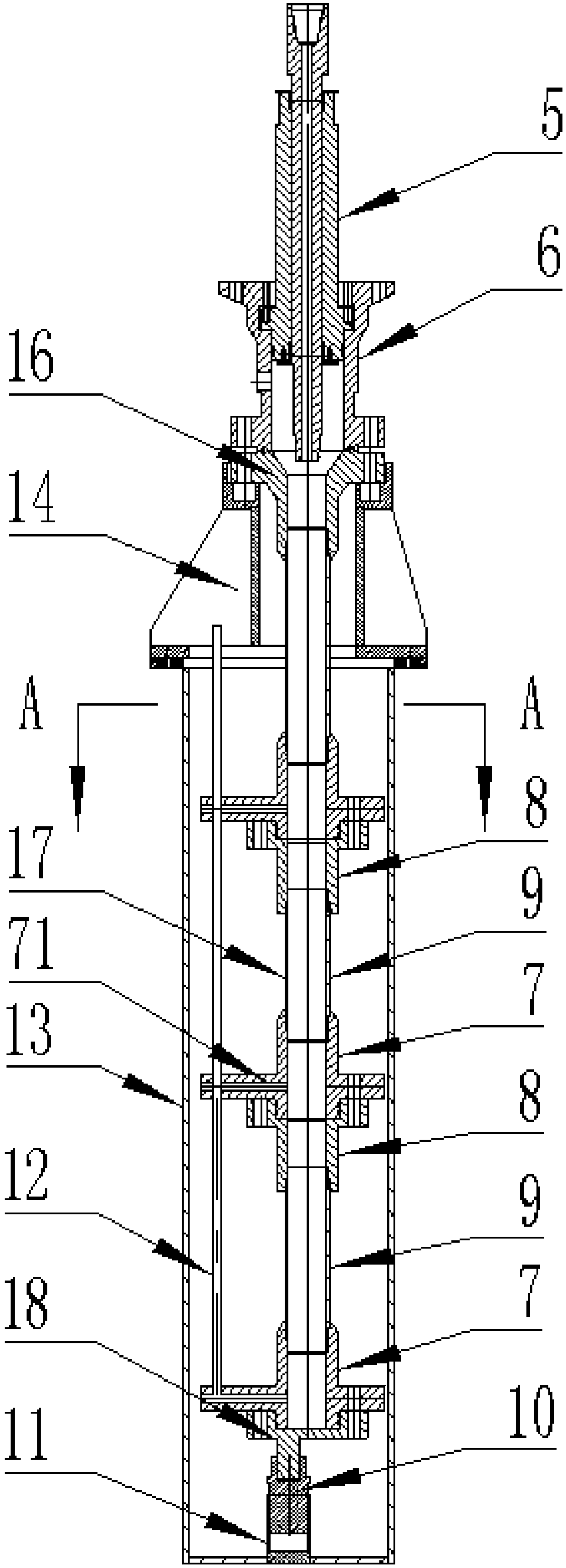
[0058] In this embodiment, the pile-based test well may be a vertical high-temperature test well, and the suitable operating temperature range is 25°C to 350°C. The wellhead device includes a hollow tube 5 and a wellhead tee 6 which are sequentially sleeved from the inside to the outside. The hollow tube 5 and the wellhead tee 6 are in an upright state, and the hollow tube 5 is sequentially sleeved with a preload disc 19, Compression cover 20 and sealing ring, compression cover 20 and described sealing ring are all positioned between hollow cylinder 5 and wellhead tee 6, and compression cover 20 can compress described sealing ring to make hollow cylinder 5 and wellhead tee 6 seal between them.

[0059] In this embodiment, the upper end of the compression cover 20 and the pre-tightening disc 19 are located above the wellhead tee 6, the compression cover 20 can move up and down relative to the hollow tube 5, and the pre-tightening disc 19 is screwed to the hollow tube 5 , along...


PUM


Abstract

The invention discloses a pile foundation type test well building method. The method comprises the following steps that 1, ground well drilling is performed through a drilling machine; 2, the drillingmachine is removed, a test outer well shaft is put down into a drilled well hole, and the position of the test outer well shaft is fixed; 3, a test inner well shaft is put down into the test outer well shaft; 4, a well mouth device is installed at the upper end of the test inner well shaft. According to the pile foundation type test well building method, the problems that an existing test well islong in building period, large in investment and not convenient to maintain and repair are solved.

Description

technical field [0001] The invention relates to the technical field of oil exploitation test and testing, in particular to a construction method of a pile-based test well. Background technique [0002] The general method of constructing ordinary test wells is to use indoor construction above the ground 204 to install. When using this method, ordinary test wells must be equipped with infrastructure to ensure that the working environment is indoors, such as figure 1 As shown, the common test well in this construction includes a wellhead cross 201 , a surface process pipeline 202 and a test wellbore 203 . (Forcibly installed outdoors will lead to frequent maintenance, increase project operating costs, and reduce service life.) The disadvantage of this method is that the project construction period is long, supporting funds are large, and land occupation is large. Moreover, limited by the operating space, it is very difficult to maintain and replace parts of the equipment. Co...

Claims


Application Information

Patent Timeline
Patent Type & Authority Applications(China)
IPC IPC(8): E21D1/03E21D5/00E21D7/00
CPCE21D1/03E21D5/00E21D7/00
Inventor 朱富林郑亮杨俊蔡德春冯久鸿李彪刘卫红赵峰周坤王斌曲玉辰常鹏梅王昊陈健曹建郭津瑞刘丽侯兴卫
Owner PETROCHINA CO LTD
Why Eureka
Try Eureka