Oil fume extraction device equipped with distribution plate arranged in front of suction opening

A technology for suction holes and oil fume extraction, which is applied to the components of pumping devices for elastic fluids, oil fume removal, and household heating, etc., to achieve the effect of improving separation ability and high separation ability.

Inactive Publication Date: 2018-03-23
BERLING AERO IP UG HAFTUNGSBESCHRANKT
View PDF8 Cites 2 Cited by
  • Summary
  • Abstract
  • Description
  • Claims
  • Application Information

AI Technical Summary

Problems solved by technology

However, it has not been possible so far to completely separate the oil and fat particles and other aerosols transported in the exhaust gas flow.

Method used


Image

  • Oil fume extraction device equipped with distribution plate arranged in front of suction opening
  • Oil fume extraction device equipped with distribution plate arranged in front of suction opening

Examples


Embodiment Construction

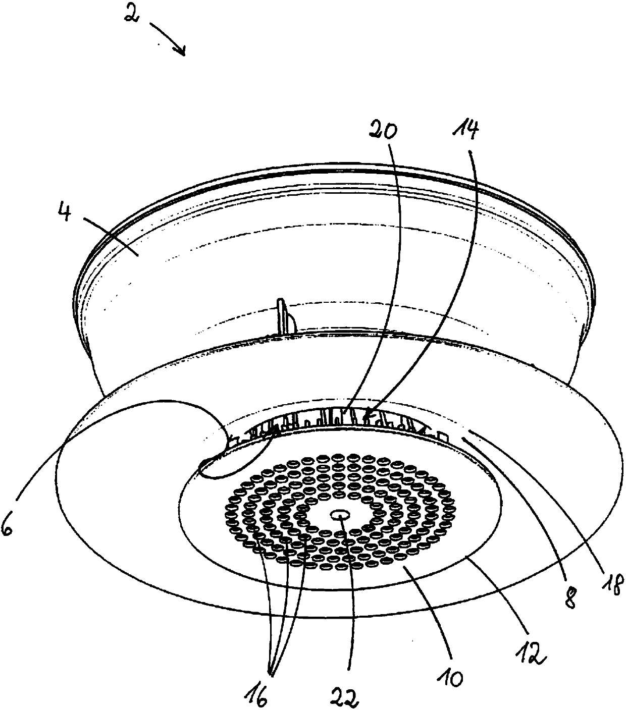
[0025] exist figure 1 The view from obliquely below shows the cooker hood 2 . The range fume extraction device 2 is composed of a housing 4 having a suction hole 6 . The cooker hood 2 is arranged above the cooking zone in such a way that the suction opening 6 faces the cooking zone. The suction opening 6 is surrounded on the peripheral side by an inflow lip 8 . The inflow lip 8 forms an approximately funnel-shaped suction channel on the suction side that narrows in the direction of flow, which continues into the interior of the hood 2 .

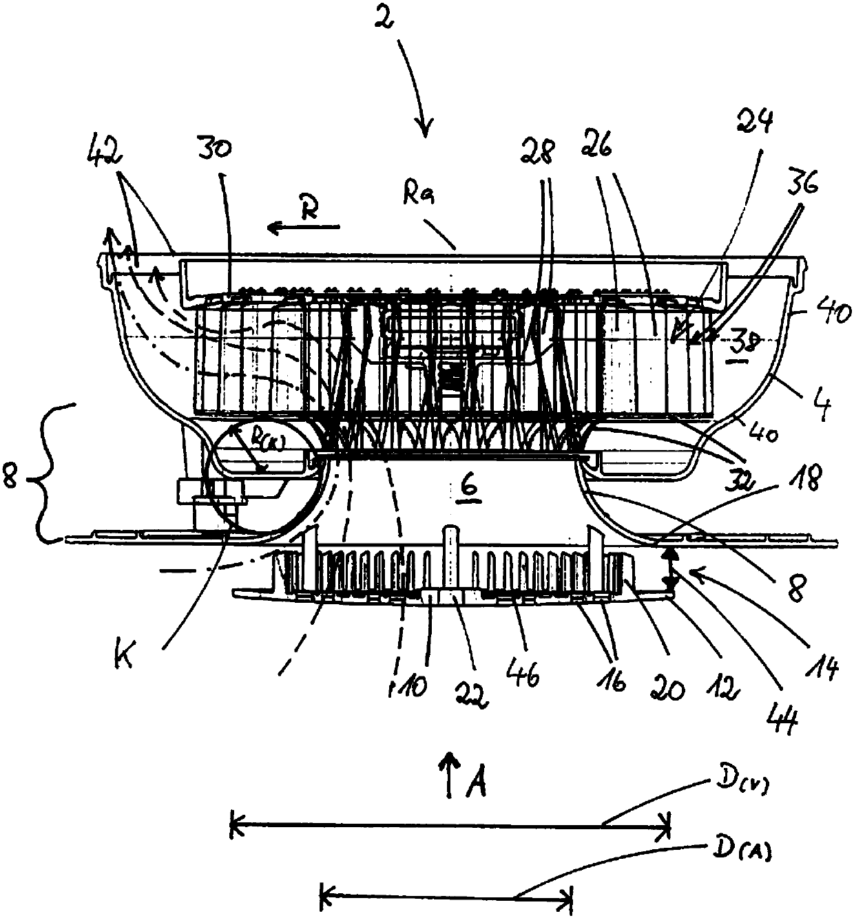
[0026] Suction hole 6 in figure 1The view shown in is covered by the distribution plate 10 . In this embodiment, the distribution plate 10 has a circular shape, which also applies to the suction holes 6 . In this embodiment, the distribution plate 10 has a larger diameter than the suction holes 6 , so that the distribution plate 10 with its outer edge 12 extends completely beyond the curvature of the inflow lip 8 in the vertical directio...


PUM


Abstract

The present invention relates to an oil fume extraction device (2) equipped with a suction opening (6) and a motor-driven fan arranged in a housing (4).The fan is a radial fan arranged in the housing(4) with a fan wheel (24), which are provided air blades (26) concentrically around a rotation axis (Ra). In order to improve the separation efficiency of the extraction device through an optimized air flow of the exhaust air flow through the radial fan, it is proposed that the suction opening (6) is preceded by a distribution plate (10) having a diameter D (V) corresponding to a diameter D(A) ofthe suction opening (6);an outer edge (12) of the distributor plate (10) maintains an annular clearance gap (14) relative to the outer contour of an inflow lip (8); an air flow passes through the clearance gap to flow into the inflow lip (8) to the suction opening (6); the distribution plate (10) is designed to be closed in the outer peripheral region and in the inner region provided with one or more inflow openings (16) through which the exhaust air flow flows into the central region of the suction opening (6).

Description

technical field [0001] The invention relates to a range fume extractor with a suction hole and a motor-driven fan arranged in a casing, wherein the fan is a radial fan arranged in the casing with a fan impeller having Air vanes arranged concentrically around an axis of rotation (R), wherein mutually adjacent air vanes delimit a through-flow space between them, the through-flow space being delimited at the upper and lower ends of the air vanes by corresponding cover plates , and wherein the inflow-side outer cover plate has an arcuate bend open towards the suction opening, which continues through the housing to the inflow lip through the funnel-shaped shape of the inflow-side cover plate of the fan impeller, The inlet lip has an at least approximately semicircular cross-sectional shape and limits the suction opening, and the fan wheel is in operation [0002] - the exhaust air is sucked axially through the central suction hole facing the cooking zone, [0003] - deflects the ...

Claims


Application Information

Patent Timeline
IPC IPC(8): F24C15/20
CPCF24C15/2042F04D29/4213F04D29/4253F04D29/441F04D29/703F05D2260/602F05D2260/607F24C15/20
Inventor 贝林格·尤多
Owner BERLING AERO IP UG HAFTUNGSBESCHRANKT
Why Eureka
Try Eureka