
Cooling and blowing device for radar level gauge and material level detection system

A technology of material level gauge and radar, which is applied in the field of material level detection, can solve the problems of inability to guarantee the detection accuracy of radar level gauge, sudden drop of cooling and sweeping effect, waste of energy, etc., achieve simple structure, reduce energy consumption, and manufacture convenient effect

Active Publication Date: 2018-03-23
BAOTOU ENG & RES CORP OF IRON & STEEL IND CHINA METALLURGY CONSTR GROUP BERIS
View PDF6 Cites 3 Cited by
  • Summary
  • Abstract
  • Description
  • Claims
  • Application Information

AI Technical Summary

Problems solved by technology

But the cooling and purging device ignores the interference of the pressure fluctuation in the sealed container to the cooling and purging device. The output pressure of the air outlet for cooling and purging) remains unchanged, so that the amount of gas entering the sealed container drops instantly, forcing its cooling and sweeping effect to drop sharply, and even the detection accuracy of the radar level gauge cannot be guaranteed; and when the sealed container When the internal pressure drops, and because the sweeping intensity of the cooling and purging device remains unchanged, the amount of gas entering the sealed container rises instantaneously, but the sweeping of the radar level gauge does not require so much gas at all, resulting in a large amount of excess gas Into a sealed container, extremely wasteful of energy

Method used


Image

  • Cooling and blowing device for radar level gauge and material level detection system
  • Cooling and blowing device for radar level gauge and material level detection system
  • Cooling and blowing device for radar level gauge and material level detection system

Examples


Embodiment Construction

[0029] Specific embodiments of the present invention will be described in detail below in conjunction with the accompanying drawings.

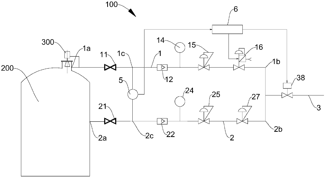
[0030] figure 1 A material detection system according to the present invention and an existing sealed container are shown. Such as figure 1 As shown, the material detection system includes a radar level gauge 300 and a cooling and purging device 100, wherein the radar level gauge 300 is installed on the top of the sealed container 200, and the cooling and purging device 100 is used to cool and purge the radar level gauge 300 The transceiver end (that is, the receiving and transmitting end) to reduce the influence of high temperature, dirty, humid and pressurized gas on the radar level gauge 300. The cooling and purging device 100 mainly includes a first branch 1 with a flow regulating valve 16 , a second branch 2 with a pressure reducing valve 27 , a dry circuit 3 , a differential pressure transmitter 5 and a controller 6 .

[0031] The gas...


PUM


Abstract

The invention relates to a cooling and blowing device for a radar level gauge and a material level detection system. The cooling and blowing device comprises a first branch circuit which is provided with a flow regulating valve and a first opening and installed on a sealed container, a second branch circuit which is provided with a reducing valve and a second opening and installed on the side wallof the sealed container, a main circuit connected with air inlets of the first branch circuit and the second branch circuit so as to receive gas, a differential pressure transmitter and a controller,wherein two pressure measuring openings of the differential pressure transmitter are connected with the first opening and the second opening respectively, and the controller is connected with the differential pressure transmitter and the flow regulating valve. The controller can regulate the opening of the flow regulating valve according to a detection value of the differential pressure transmitter, the air outlet of the first branch circuit cools and blows the transceiving end of the radar level gauge so as to lower the influence of gas with high temperature, dirt, moisture and pressure inside the sealed container on the radar level gauge, pressure changes of the air outlet of the first branch circuit are in positive correlation with pressure changes inside the sealed container, and therefore the purpose of lowering energy consumption is achieved.

Description

technical field [0001] The invention belongs to the technical field of material level detection, and in particular relates to a detection device and a material level detection system for a material level in a sealed container. Background technique [0002] The radar level gauge transmits high-frequency pulses from the radar antenna, propagates in space at the speed of light, reaches the measured object and reflects back, and detects the distance and material level through the time required for pulse propagation. Traditional radar level gauges are widely used, and the detection effect is better, but when detecting the material level of materials in high-temperature, dirty, wet and pressurized sealed containers (such as reaction tanks or reactors, etc.), due to the high temperature in the sealed container, Large dust and high humidity make it very easy to interfere with the detection of the radar level gauge and affect the detection accuracy of the radar level gauge. [0003]...

Claims


Application Information

Patent Timeline
IPC IPC(8): G01F23/284F25D3/10
CPCF25D3/10G01F23/284
Inventor 任尚业
Owner BAOTOU ENG & RES CORP OF IRON & STEEL IND CHINA METALLURGY CONSTR GROUP BERIS
Learn More