
Operation device of direct current circuit breaker and operation method of operation device

A technology for DC circuit breakers and controllers, which is applied in the direction of high-voltage air circuit breakers, circuits, high-voltage/high-current switches, etc. Unable to achieve rated opening and closing, etc., to achieve the effect of small mass, simple structure and fast speed

Active Publication Date: 2018-03-23
XI AN JIAOTONG UNIV
View PDF7 Cites 27 Cited by
  • Summary
  • Abstract
  • Description
  • Claims
  • Application Information

AI Technical Summary

Problems solved by technology

This patent is based on the fast repulsion switch held by permanent magnets, which can effectively increase the opening speed of the switch, but the patent cannot achieve rated opening and closing. At the same time, it can quickly open when the short-circuit fault current arrives, and on the premise of realizing the two functions, Realize long service life of rated opening and closing, fast opening, small mass and fast speed of movable parts, improve service life of DC circuit breaker, reduce closing speed
[0005] The current quick operating mechanism is difficult to meet the life requirements of rated opening and closing on the basis of realizing quick opening and closing
In some occasions that require frequent on-off, it cannot be better compatible with the requirements of high rated opening and closing life and fast opening and closing speed.

Method used


Image

  • Operation device of direct current circuit breaker and operation method of operation device
  • Operation device of direct current circuit breaker and operation method of operation device
  • Operation device of direct current circuit breaker and operation method of operation device

Examples


Embodiment Construction

[0036] Specific embodiments of the present invention will be described in more detail below with reference to the accompanying drawings. Although specific embodiments of the invention are shown in the drawings, it should be understood that the invention may be embodied in various forms and is not limited to the embodiments set forth herein. Rather, these embodiments are provided for more thorough understanding of the present invention and to fully convey the scope of the present invention to those skilled in the art.

[0037] It should be noted that certain terms are used in the specification and claims to refer to specific components. Those skilled in the art should understand that they may use different terms to refer to the same component. The specification and claims do not use differences in nouns as a way of distinguishing components, but use differences in functions of components as a criterion for distinguishing. "Includes" or "comprises" mentioned throughout the spe...


PUM


Abstract

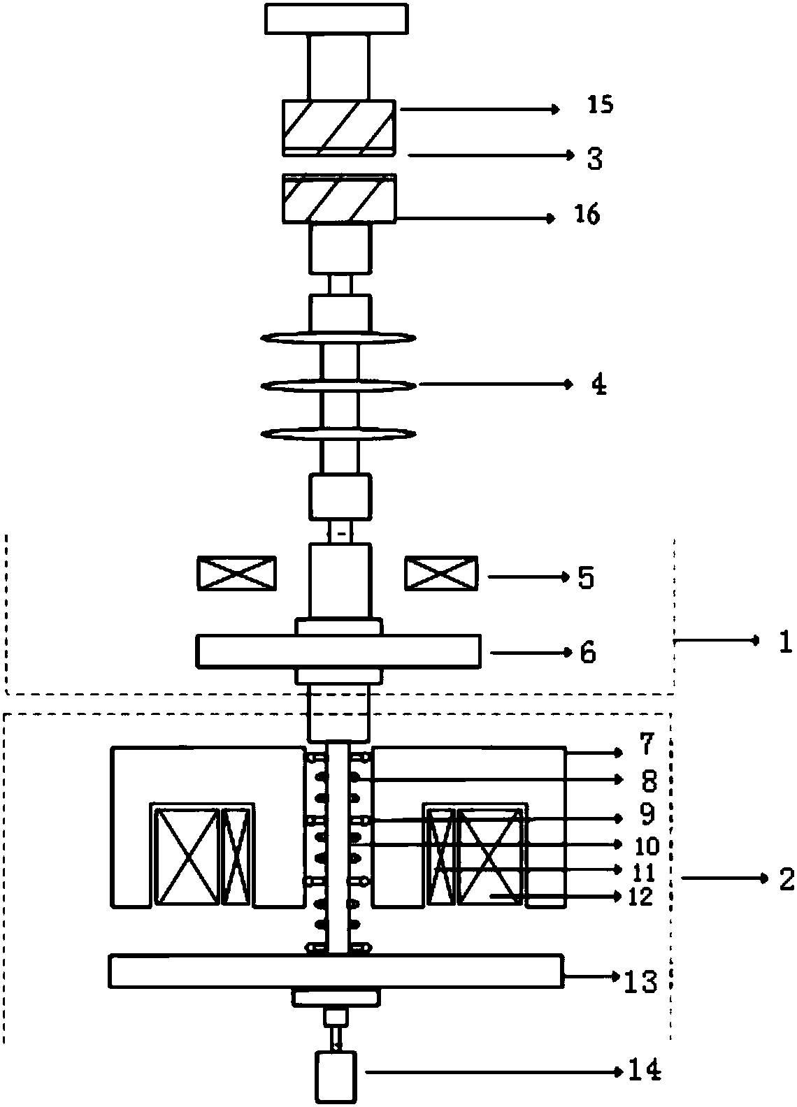
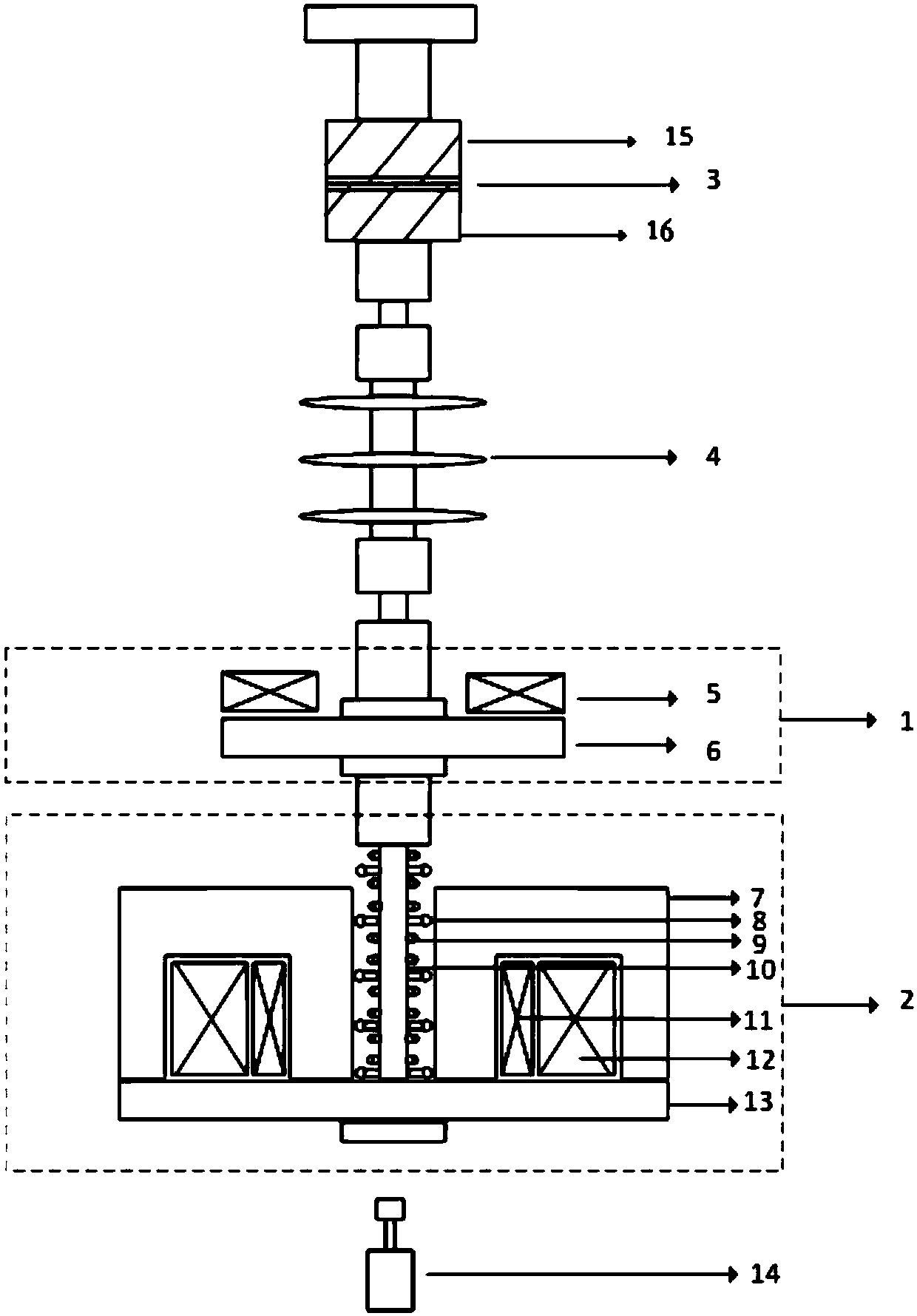
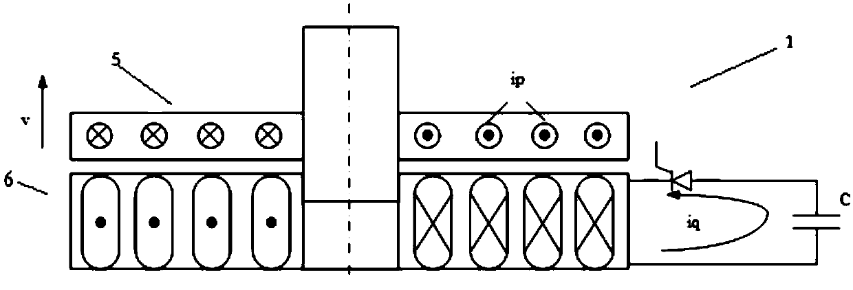
The invention discloses an operation device of a direct current circuit breaker and an operation method of the operation device. The operation device comprises a vacuum bubble, a repulsion device andan electromagnetic mechanism connected with the repulsion mechanism through a connection rod. A mechanical contact consisting of a static contact and a moving contact is arranged in the vacuum bubble.The moving contact is connected with the repulsion mechanism through an insulation pull rod. The repulsion mechanism comprises a separating coil, a repulsion disc, a charging / discharging loop and a first controller controlling the charging / discharging loop to trigger the separating coil. The repulsion disc is connected with the connection rod through a moving guidance rod. The separating coil isarranged on the repulsion disc and the gap is not more than 3.5 mm. The electromagnetic mechanism comprises an annular hollow static iron core, a moving iron core, an attracting coil, a keeping coil,a separating reset coil, a contact spring and a second controller.

Description

technical field [0001] The invention relates to the field of a DC circuit breaker, in particular to an operating device and an operating method for a DC circuit breaker. Background technique [0002] Due to the low cost of the DC system, no capacitive current, no eddy current loss, and easier control of the power flow, the DC HVDC transmission system has attracted much attention. Especially in some specific occasions, such as large-scale ship power supply system, urban rail transit power supply system and other DC systems have been greatly developed. At the same time, with the continuous increase of the capacity of the DC system and the continuous improvement of the voltage level, the peak value of the short-circuit current can reach more than 100kA, and the rate of increase of the short-circuit current is also more than 15A / us. [0003] Patent document CN201156495Y discloses an operating mechanism in a circuit breaker comprising an electromagnetic repulsion driving mechani...

Claims


Application Information

Patent Timeline
Patent Type & Authority Applications(China)
IPC IPC(8): H01H33/666
CPCH01H33/666
Inventor 吴翊杨飞吴益飞纽春萍康旭峰易强
Owner XI AN JIAOTONG UNIV
Learn More