Multifunctional pot

A multifunctional pot and pot body technology, which is applied in the field of kitchen utensils, can solve the problems of uneven heating of the pot body, uneven heating of the pot body, and low energy utilization rate, so as to avoid uneven heating, reduce heat transfer, and improve energy utilization. high rate effect

Pending Publication Date: 2018-03-27
NINGBO JINYU ELECTRIC APPLIANCE
View PDF6 Cites 70 Cited by
  • Summary
  • Abstract
  • Description
  • Claims
  • Application Information

AI Technical Summary

Problems solved by technology

Existing multifunctional pots generally have a shell and a pot body, and some multifunctional pots directly heat the pot body through a heater for cooking. This method is likely to cause uneven heating of the pot body; A heat-conducting liner is set in between, and a heater is set on the outer wall of the liner, which solves the problem of uneven heating of the pot body to a certain extent, but since the heater is set between the heat-conducting liner and the outer shell, the heat of the heater A large part will be dissipated to the surrounding through the shell, the heat loss is large, the energy utilization rate is low, the work efficiency is low, and the shell temperature is high, and the integrity is poor

Method used


Image

  • Multifunctional pot
  • Multifunctional pot
  • Multifunctional pot

Examples


Embodiment 1

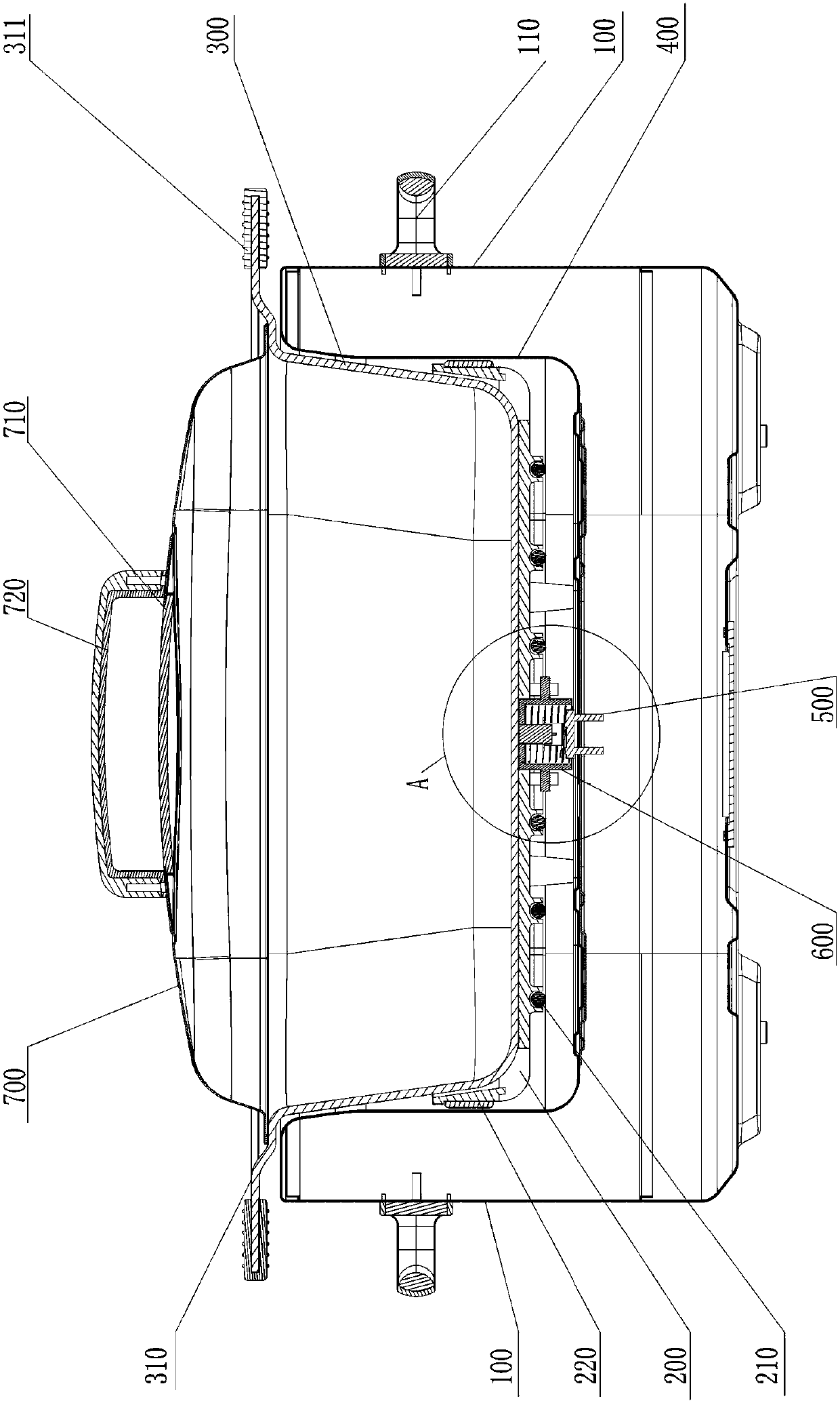
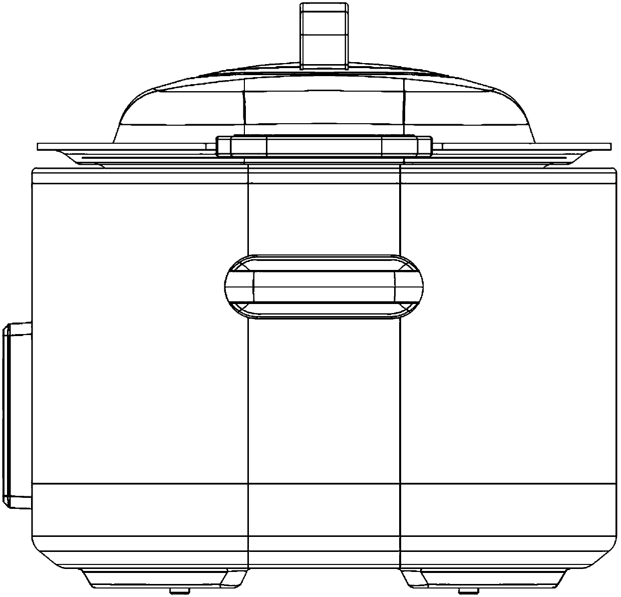
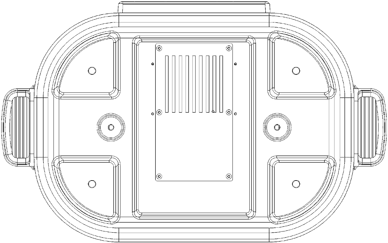
[0030] This embodiment provides a multifunctional pot, such as Figure 1-7 As shown, it includes a casing 100, a heating element heat conducting plate 200 and a pot body 300. An inner container 400 is arranged inside the casing 100, and the upper end of the casing 100 is connected to the upper end of the inner container 400; And the height of the heating element heat conducting plate 200 is lower than the depth of the inner tank 400, the outer bottom surface of the heating element heat conducting plate 200 is provided with a bottom heating element 210 for heating the bottom of the heating element heat conducting plate 200, and on the outer wall of the heating element heat conducting plate 200 There is an annular heating element 220 for heating the side wall of the heating element heat conduction plate 200, the bottom heating element 210 and the annular heating element 220 are connected in parallel and electrically connected to the working circuit of the multifunctional pot; Th...


PUM


Abstract

The invention discloses a multifunctional pot. The pot includes a housing, a heating element heat conduction disk and a pot body, a liner is arranged in the housing, and the upper end of the housing is connected with the upper end of the liner; the heating element heat conduction disk is arranged in the liner, the height of the heating element heat conduction disk is lower than the depth of the liner, a bottom heating element is arranged at the outer bottom of the heating element heat conduction disk, an annular heating element is arranged on the outer side wall of the heating element heat conduction disk, and the bottom heating element and the annular heating element are in series connection and are electrically connected to a working circuit of the multifunctional pot; the pot body is arranged on the heating element heat conduction disk, the inner wall of the heating element heat conduction disk is in contact with the outer wall of the pot body, and the height of the pot body is larger than the depth of the heating element heat conduction disk. The heating element heat conduction disk of the multifunctional pot directly heats the pot body evenly, the inner wall of the heating element heat conduction disk can be in close contact with the outer wall of the pot body, hence, most of heat can be transmitted to the pot body, the liner can effectively keep the heating element from transmitting heat to the outside world, the heat loss is small, and the energy utilization rate is high.

Description

technical field [0001] The invention relates to the technical field of kitchen utensils, in particular to a multifunctional pot. Background technique [0002] A multi-function pot is a modern kitchen utensil that can realize multiple processes such as frying, frying, steaming, and boiling. Generally, each function has at least two gears, which can meet the multi-faceted requirements of users and greatly facilitate people. life. Existing multifunctional pots generally have a shell and a pot body, and some multifunctional pots directly heat the pot body through a heater for cooking. This method is likely to cause uneven heating of the pot body; A heat-conducting liner is set in between, and a heater is set on the outer wall of the liner, which solves the problem of uneven heating of the pot body to a certain extent, but since the heater is set between the heat-conducting liner and the outer shell, the heat of the heater A large part will be dissipated to the surrounding thro...

Claims


Application Information

Patent Timeline
Patent Type & Authority Applications(China)
IPC IPC(8): A47J27/00A47J36/24
CPCA47J27/004A47J36/2483A47J36/32H05B3/68
Inventor 施军达施钟毓柳树阔李兵雄
Owner NINGBO JINYU ELECTRIC APPLIANCE
Why Eureka
Try Eureka