Aeroengine blisk disintegrating device

An aero-engine and integral blisk technology, which is applied to hand-held tools, manufacturing tools, etc., can solve the problems of unfavorable decomposition of loosening force, occupying a large space, and requiring a crane, shortening decomposition time, improving production efficiency, and reducing labor intensity. Effect

Inactive Publication Date: 2018-03-27
AECC AVIATION POWER CO LTD
View PDF13 Cites 2 Cited by
  • Summary
  • Abstract
  • Description
  • Claims
  • Application Information

AI Technical Summary

Problems solved by technology

The disadvantage of this decomposition method is that the bearing surface is far away from the interference stop, and the overall blisk that acts as a support under the action of internal force is easily squeezed and deformed, which may increase the interference tightness of the stop. Therefore, a larger The loosening force is not conducive to the decomposition of the overall blisk; the overall blisk has a large diameter, in order to ensure the strength of the puller, the support plate is designed to be thicker, resulting in a large weight of the puller, which requires a crane during use and is inconvenient to operate; for high-pressure compressor rotor stage There are a large number, each level has a different structure, and each level requires a different puller. A complete set of pullers weighs several hundred kilograms, which not only takes up a lot of space, but also is inconvenient to transport; the hooks of the pullers are segmented structures, and must exceed the length of the blades. To be able to touch the edge of the blade, multiple people are required to cooperate with the operation at the same time, and a little carelessness will damage the blade; during the extraction process, due to the poor stability of the threaded rod rotation process, multiple people are required to support the support plate around the puller. Ensuring that the puller hooks do not become unhooked
The process of decomposing the blisk has great safety hazards, and it is time-consuming and labor-intensive, and the efficiency is very low

Method used


Image

  • Aeroengine blisk disintegrating device
  • Aeroengine blisk disintegrating device
  • Aeroengine blisk disintegrating device

Examples


Embodiment Construction

[0033] The present invention will be described in detail below in conjunction with the accompanying drawings and specific embodiments.

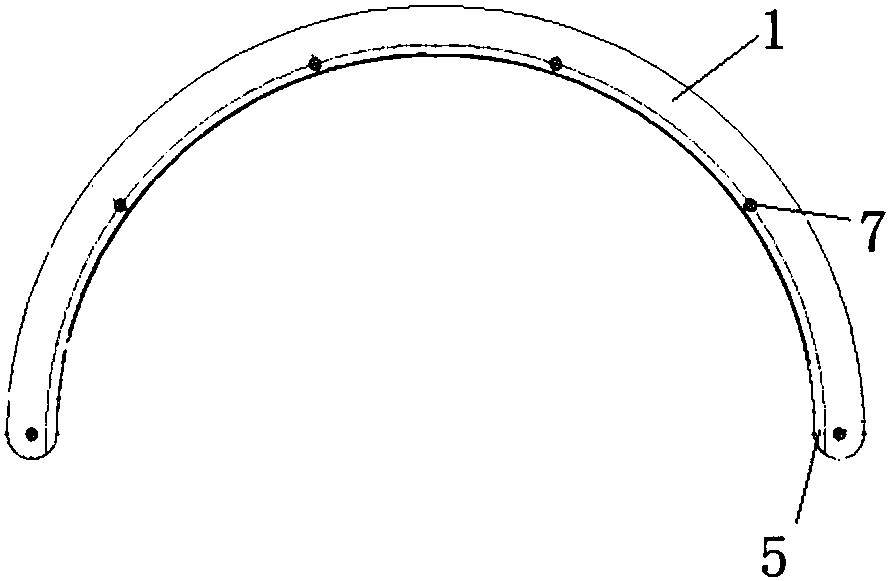
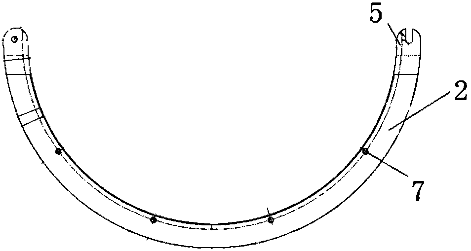
[0034] refer to Figure 1 to Figure 7, the whole blisk decomposition device of aero-engine includes left half ring 1 and right half ring 2, the diameter and thickness of left half ring 1 and right half ring 2 are the same, the thickness of left half ring 1 and right half ring 2 is according to two phases The distance between the adjacent blisks, the height of the studs and the smooth pressure block 4 is determined, the thickness of the left half ring 1 and the right half ring 2 meet the requirement that the fixed stud 3 does not unscrew the left and right half rings during the height adjustment process, and is The tool for rotating the nut of the fixed stud 3 leaves enough room for operation. There are 4 evenly arranged M8 threaded holes 7 on the left half ring 1 and the right half ring 2 respectively, which can be adjusted according to the d...


PUM


Abstract

The invention discloses an aeroengine blisk disintegrating device comprising a left half ring and a right half ring. Positioning holes are formed in the two ends of the left half ring and the right half ring correspondingly, and the left half ring and the right half ring are connected into a circular ring through the positioning holes and order type screws, are the same in diameter and thickness and are each provided with a plurality of thread holes. The thread holes are in threaded fit with fixing studs, adjacent blisks are disintegrated through adjustment of the heights of the studs, and thesituation that the blisks greatly deform to increase loosening force in the disintegration process cannot not be caused because the force applying face is close to an interference spigot. The aeroengine blisk disintegrating device is low in weight, small in occupied area, easy and convenient to operate, safe, reliable and capable of improving the blisk disintegrating work efficiency.

Description

technical field [0001] The invention belongs to the technical field of assembly, and in particular relates to an aeroengine integral blisk disassembly device. Background technique [0002] Integral blisks have been used as a major improvement component of new aero-engines, not only for models under research, but also for future high-thrust-to-weight ratio engines. Integral blisks are designed with the blades and discs of the engine rotor as a whole, and are manufactured by integral processing or welding, without processing tenons and tenons. The advantages of this overall structure are: the radial height and thickness of the rim of the blisk and the size of the original tenon of the blade can be greatly reduced, and the weight reduction effect is obvious; the structure of the engine rotor parts is greatly simplified; the split structure tenon is eliminated The escape loss of gas in the tooth root gap; avoids the failure caused by fretting wear, cracks and lock piece damage ...

Claims


Application Information

Patent Timeline
Patent Type & Authority Applications(China)
IPC IPC(8): B25B27/02
Inventor 王满贤谈军高云锋李永民闫艳李荣杨翠玲王凯
Owner AECC AVIATION POWER CO LTD
Why Eureka
Try Eureka