Polymer material smashing and screening device

A screening device and polymer technology, applied in the field of material crushing and screening device and polymer material crushing and screening device, can solve the problems of poor crushing effect and complicated operation, and achieve novel design, improved crushing effect and reasonable structure. Effect

Pending Publication Date: 2018-03-27
洛阳乐森石化新材料有限公司
0 Cites 4 Cited by

AI-Extracted Technical Summary

Problems solved by technology

[0003] A variety of different substances are mixed in the polymer material, and the polymer material needs to be crushed and sieved. The crushing effect of the general crushing device may n...

Abstract

The invention discloses a polymer material crushing and screening device, which comprises a fixed frame, a shell, a hopper, an electric push rod, a horizontal plate, a first motor, a screening shell, a first cavity, a second cavity, The third cavity, the top cover, the first through hole, the second through hole, the second motor, the cutting shaft, the blade, the first bearing, the inclined plate, the grinding wheel, the rotating shaft, the separator, the fixed block, the third motor, the bottom plate and second bearing. The invention has a reasonable structure. The material can be preliminarily chopped by the blade on the cutting shaft, and then ground by two grinding wheels. After the grinding, the grinding wheel and the fixed block are used for grinding again. Through three times of treatment, the quality of the material can be improved. Crushing effect: through the funnel hopper, the crushed material can directly enter the first cavity, and the material can be sieved without the need for power device for transportation. The material can be sieved through the first through hole and the second through hole, Material that does not pass the size is allowed to accumulate in the first cavity, the second cavity and the third cavity.

Application Domain

Grain treatments

Technology Topic

Motor shaftAgricultural engineering +5

Image

  • Polymer material smashing and screening device
  • Polymer material smashing and screening device
  • Polymer material smashing and screening device

Examples

  • Experimental program(1)

Example Embodiment

[0021] The technical solutions in the embodiments of the present invention will be clearly and completely described below in conjunction with the accompanying drawings in the embodiments of the present invention. Obviously, the described embodiments are only a part of the embodiments of the present invention, rather than all the embodiments. Based on the embodiments of the present invention, all other embodiments obtained by those of ordinary skill in the art without creative work shall fall within the protection scope of the present invention.
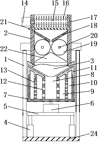
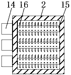
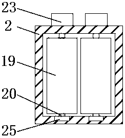
[0022] See Figure 1-3 As shown, a polymer material crushing and screening device includes a housing 2 and a fixing frame 1 fixed on the surface of the housing 2. A hopper 3 is fixed at the bottom of the housing 2 and the fixing frame 1 is fixed at the bottom. Connected to the bottom plate 24, the surface of the bottom plate 24 is fixedly connected with an electric push rod 4, the bottom plate 24 provides fixation for the electric push rod 4, the top of the electric push rod 4 is fixed with a horizontal plate 5, and the electric push rod 4 can drive the horizontal plate 5 moves in the vertical direction, the surface of the horizontal plate 5 is fixedly connected with a first motor 6, the output end of the first motor 6 is sleeved with a first output shaft, and the end of the first output shaft is fixedly connected with a screen Shell 7, the top of the screening shell 7 is in clearance fit connection with the hopper 3, the hopper 3 will not affect the rotation of the screening shell 7, and the middle of the screening shell 7 is opened with a first cavity 8. A second cavity 9 and a third cavity 10 are opened inside the screening housing 7, a first through hole 12 is opened between the first cavity 8 and the second cavity 9, and the first A second through hole 13 is opened between the second cavity 9 and the third cavity 10, and the material can be screened through the first through hole 12 and the second through hole 13. The top of the screening shell 7 is screwed with The top cover 11, the top cover 11 can seal the housing 7;
[0023] The side wall of the housing 2 is fixedly connected with a second motor 14, the output end of the second motor 14 is sleeved with a second output shaft, the end of the second output shaft is fixedly connected with a cutting shaft 15 and the surface of the cutting shaft 15 A number of blades 16 are fixedly connected, and the blades 16 can shred materials. The end of the cutting shaft 15 is sleeved with a first bearing 17, and the first bearing 17 is embedded in the inner side wall of the housing 2. The bottom of the cutting shaft 15 A partition 21 is provided. The partition 21 can block the material when the material is shredded. The bottom of the partition 21 is provided with an inclined plate 18, and the inclined plate 18 is fixed to the side wall of the casing 2. The number of the inclined plate 18 There are two, and a first gap is formed between the two inclined plates 18, and the material can enter between the two rollers 19 through the first gap. The bottom of the inclined plate 18 is provided with two rollers 19, and two rollers A second gap is formed between the wheels 19, and the first grinding of the material can be carried out by two grinding wheels 19, a third motor 23 is fixedly connected to the side wall of the housing 2, and the output end of the third motor 23 is sleeved The rotating shaft 20 is sleeved with a second bearing 25 at the end of the rotating shaft 20, and the second bearing 25 is inlaid on the inner side wall of the housing 2. The rotating shaft 20 is sleeved with the roller 19, and the bottom of the roller 19 is provided with a fixing block 22 , The fixed block 22 and the two rollers 19 form two third gaps, the material between the two rollers 19 and the fixed block 22 can be secondly milled, and the width of the third gap is smaller than the width of the second gap.
[0024] As a technical optimization solution of the present invention, the cross section of the fixed block 22 is an isosceles triangle structure, and the fixed block 22 is fixedly connected to the inner side wall of the housing 2, and the two grinding wheels 19 and the fixed block 22 allow the material to pass through after grinding. The third gap enters the hopper 3.
[0025] As a technical optimization solution of the present invention, the inner side wall of the housing 2 is provided with a card slot, and the card slot is engaged with the partition 21, and the partition 21 penetrates the side wall of the housing 2 to facilitate the partition 21 The drawing out facilitates the material to fall on the inclined plate 18.
[0026] As a technical optimization solution of the present invention, the aperture of the second through hole 13 is smaller than the aperture of the first through hole 12, and the second through hole 13 is in communication with the second cavity 9 and the third cavity 10, so that Materials of different sizes enter the second cavity 9 and the third cavity 10 for aggregation.
[0027] As a technical optimization solution of the present invention, the number of the electric push rods 4 is two, and the electric push rods 4 are fixed to the bottom plate 24, and the electric push rods 4 can drive the screening housing to move in the vertical direction.
[0028] As a technical optimization solution of the present invention, the hopper 3 has a conical structure, and the bottom of the hopper 3 is provided with a leakage opening, and the material can enter the first cavity 8 through the leakage opening at the bottom of the hopper 3.
[0029] As a technical optimization solution of the present invention, the first cavity 8 and the second cavity 9 are both in communication with the first through hole 12, and the top of the first cavity 8 has an open end, and the first cavity 8 passes through The first through hole 12 can allow materials smaller than the first through hole 12 to enter the second cavity 9 and gather.
[0030] As a technical optimization solution of the present invention, the second cavity 9 and the third cavity 10 are both annular structures, which can facilitate the screening of materials in the second cavity 9 and the third cavity 10 by centrifugal force.
[0031] When the present invention is in use, the electrical components in the device are externally connected to power supply and control switches, and materials are poured from the top of the housing 2, the second motor 14 drives the cutting shaft 15 to rotate through the second output shaft, and the material is initially cut through the blade 16. After crushing and shredding, the partition 21 is extracted, the material enters the second gap between the two grinding wheels 19 through the inclined plate 18, and the grinding wheel 19 drives the material through the third motor 23 to grind the material, and the ground material enters In the third gap, the fixed block 22 cooperates with the rotation of the roller 19 to grind the material a second time, and then the material enters the hopper 3, enters the first cavity 8 from the leakage port, and the first motor 6 passes through the first output shaft Drive the sieving housing 7 to rotate. Under the action of centrifugal force, the material in the first cavity 8 is screened into the second cavity 9 through the first through hole 12, and the material in the second cavity 9 passes through the second cavity. The through holes 13 are screened into the third cavity 10, so that materials of different sizes are collected in the first cavity 8, the first cavity 9 and the first cavity 10 respectively. After the screening is completed, the electric push rod 4 contracts, Keep the screening shell 7 away from the hopper 3, unscrew the top cover 11, and take out materials from the first cavity 8, the second cavity 9 and the third cavity 10.
[0032] For those skilled in the art, it is obvious that the present invention is not limited to the details of the foregoing exemplary embodiments, and the present invention can be implemented in other specific forms without departing from the spirit or basic characteristics of the present invention. Therefore, from any point of view, the embodiments should be regarded as exemplary and non-limiting. The scope of the present invention is defined by the appended claims rather than the above description, and therefore it is intended to fall within the claims. All changes within the meaning and scope of the equivalent elements of are included in the present invention. Any reference signs in the claims should not be regarded as limiting the claims involved.
[0033] In addition, it should be understood that although this specification is described in accordance with the implementation manners, not each implementation manner only includes an independent technical solution. This narration in the specification is only for clarity, and those skilled in the art should regard the specification as a whole The technical solutions in the embodiments can also be appropriately combined to form other implementations that can be understood by those skilled in the art.

PUM

no PUM

Description & Claims & Application Information

We can also present the details of the Description, Claims and Application information to help users get a comprehensive understanding of the technical details of the patent, such as background art, summary of invention, brief description of drawings, description of embodiments, and other original content. On the other hand, users can also determine the specific scope of protection of the technology through the list of claims; as well as understand the changes in the life cycle of the technology with the presentation of the patent timeline. Login to view more.

Similar technology patents

High capacity three-dimensional parking garage

Owner:QUZHOU LECHUANG ENERGY SAVING TECH

Double-mould turnover casting machine for casting piston

Owner:SHIJIAZHUANG JINGANG KAIYUAN POWER SCI & TECH

Bearing outer ring cleaning device

ActiveCN106583286AReasonable structureclean well
Owner:安徽千禧精密轴承制造有限公司

Classification and recommendation of technical efficacy words

  • Reasonable structure
  • Innovative design
Why Eureka
Try Eureka