Pulverized coal pyrolyzing furnace with material homogenizing and pressure bearing structure

A technology of pressure-bearing structure and pyrolysis furnace, which is applied in the field of pyrolysis, can solve the problems of increased impact on equipment and furnace body, weakened ability of operating pressure, buffering of radiant tubes, etc. The effect of strengthening the solution reaction and avoiding erosion and wear

Pending Publication Date: 2018-03-27
北京神雾电力科技有限公司
View PDF0 Cites 0 Cited by
  • Summary
  • Abstract
  • Description
  • Claims
  • Application Information

AI Technical Summary

Problems solved by technology

Due to the design characteristics of the furnace body, the horizontal interval of the radiant tubes in the local area of ​​the furnace suddenly increases, and there is a large gap area, so that the pulverized coal falling here cannot collide with the radiant tubes well, which will bring The following problems: 1. Since the pulverized coal cannot collide with the radiant tube well, the falling speed cannot be buffered by the radiant tube, so that the time for the pulverized coal to pass through the heating furnace is accelerated, which is far less than the optimal shutdown time of the pulverized coal (5-10s ); Secondly, due to the inability to contact the radiant tube, the heating effect of the pulverized coal in this area becomes poor, and finally the pyrolysis reaction cannot be fully carried out, and the product quality is not good; 2. Since the pulverized coal cannot collide well with the radiant tube Contact, the falling speed cannot be effectively buffered, the falling speed becomes faster, the impact on the equipment and the furnace body that hits the collision is increased, and the consumption of the equipment and the furnace body is increased; 3. Since there is no radiant tube structure in the gap area, the The ability of this part to withstand the internal operating pressure of the furnace body is weakened, thereby reducing the ability of the entire furnace body to withstand the internal operating pressure

Method used


Image

  • Pulverized coal pyrolyzing furnace with material homogenizing and pressure bearing structure
  • Pulverized coal pyrolyzing furnace with material homogenizing and pressure bearing structure
  • Pulverized coal pyrolyzing furnace with material homogenizing and pressure bearing structure

Examples


Embodiment Construction

[0029] In order to enable those skilled in the art to better understand the technical solutions of the present invention, the present invention will be further described in detail below in conjunction with specific embodiments. The embodiments described below are exemplary only for explaining the present invention and should not be construed as limiting the present invention. If no specific technique or condition is indicated in the examples, it shall be carried out according to the technique or condition described in the literature in this field or according to the product specification.

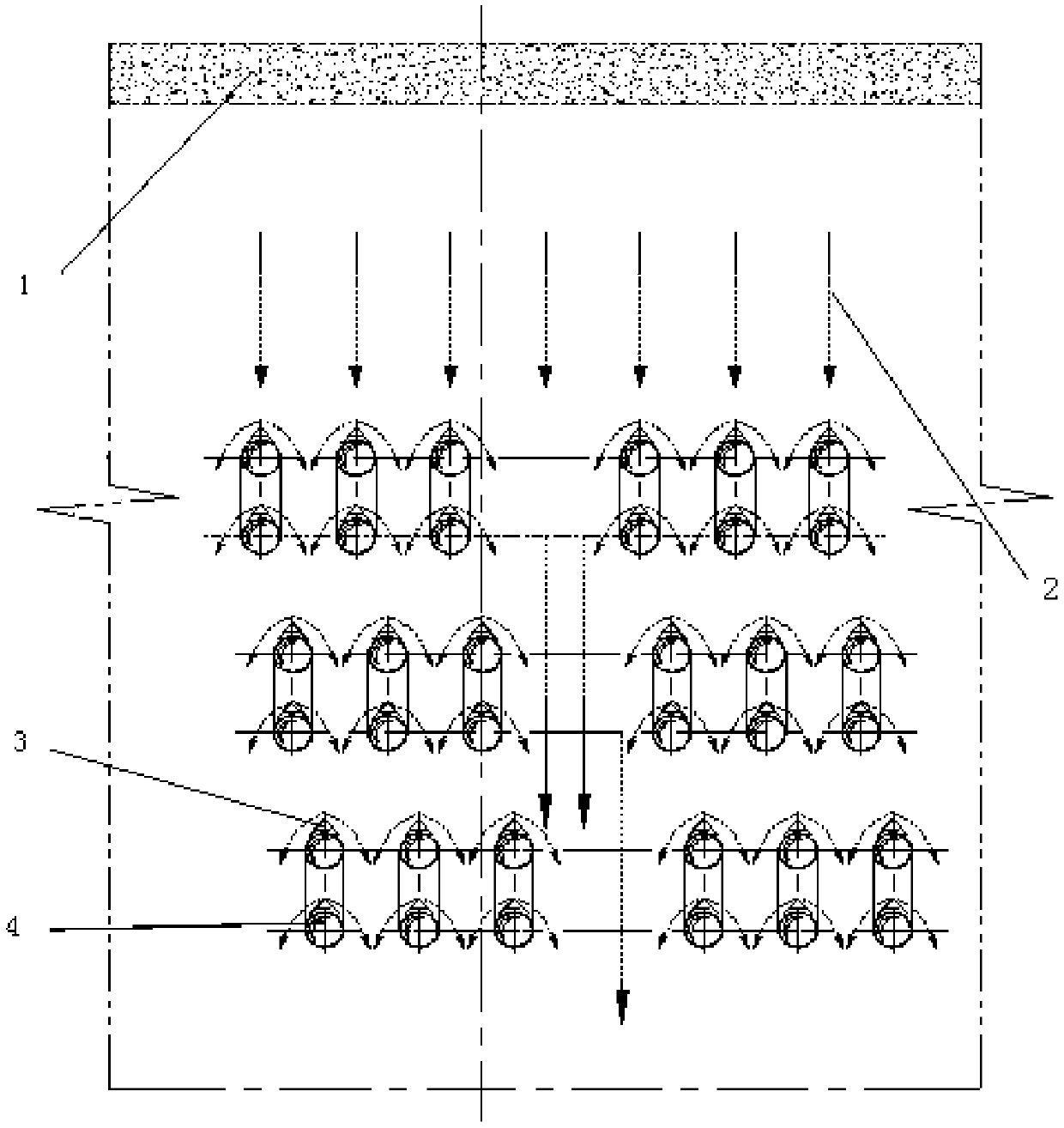
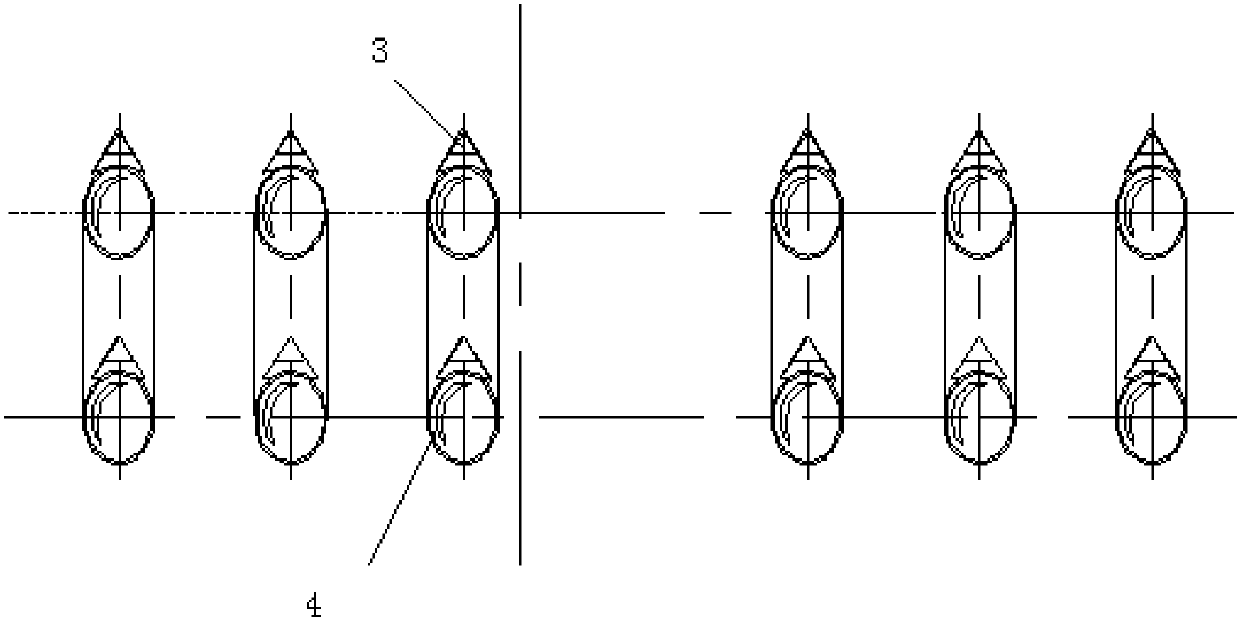
[0030] According to an embodiment of the present invention, figure 1 It is a structural schematic diagram of a pyrolysis furnace in the prior art, figure 2 for figure 1 Partial enlarged view, refer to figure 1 and 2 As shown, the multi-layer radiant tubes are arranged at intervals in the furnace cavity and form a gap area. It can be understood that the gap area is the horizontal interv...


PUM

PropertyMeasurementUnit
angleaaaaaaaaaa
diameteraaaaaaaaaa

Abstract

The invention relates to a pulverized coal pyrolysis furnace with uniform material and pressure-bearing structure, which mainly includes: a furnace body, a radiant tube, and a material-leveled and pressure-bearing structure, wherein the multi-layered radiant tube is arranged in the furnace cavity and forms a hollow In the gear area, the uniform material and pressure-bearing structure is arranged in the neutral gear area, and the uniform material and pressure-bearing structure includes: a support part, a distribution cap and a connecting part, wherein the support part is arranged along the horizontal direction; the The head of the material distribution cap is arc-shaped, and the bottom of the material distribution cap is arranged on the support part; the connecting part is fixed on the furnace wall, and is respectively connected to the two sides of the support part through pin shafts. The ends are connected, and the supporting part is fixed on the furnace wall. In the present invention, by arranging material distribution and pressure-bearing structures in the neutral area, the pulverized coal can be evenly divided and buffered, and the impact loss of the pulverized coal to the equipment and the furnace body collided; at the same time, the furnace body is strengthened. Furnace operating pressure bearing capacity, has the function of stabilizing the furnace body.

Description

technical field [0001] The invention relates to the technical field of pyrolysis, in particular to a pulverized coal pyrolysis furnace with a uniform material and a pressure-bearing structure. Background technique [0002] refer to figure 1 and 2 As shown, the granular material (powdered coal) falls directly to the upper surface of the radiant tube or touches and scours the radiant tube to be heated to the reaction temperature, so that the pyrolysis reaction occurs. The main heat transfer methods in the process are heat conduction and heat radiation. Due to the design characteristics of the furnace body, the horizontal interval of the radiant tubes in the local area of ​​the furnace suddenly increases, and there is a large gap area, so that the pulverized coal falling here cannot collide with the radiant tubes well, which will bring The following problems: 1. Since the pulverized coal cannot collide with the radiant tube well, the falling speed cannot be buffered by the ra...

Claims


Application Information

Patent Timeline
Patent Type & Authority Applications(China)
IPC IPC(8): C10B53/04
CPCC10B53/04
Inventor 吴道洪彭远旺林景龙
Owner 北京神雾电力科技有限公司
Why Eureka
Try Eureka