Control system for ultrasonic transducer dead zone

A control system, ultrasonic technology, applied in the direction of using ultrasonic/sonic/infrasonic waves, instruments, measuring devices, etc., can solve problems such as unrecognizable, ultrasonic echo signal submersion, measurement failure, etc., to reduce the measurement blind area and small measurement blind area , good reliability

Inactive Publication Date: 2018-03-27
GUANGHAN SIKE XINDA TECH CO LTD
View PDF0 Cites 2 Cited by
  • Summary
  • Abstract
  • Description
  • Claims
  • Application Information

AI Technical Summary

Problems solved by technology

If the aftershock amplitude of the ultrasonic transducer is still greater than the maximum amplitude of the ultrasonic echo signal, the ultrasonic echo signal will be submerged and cannot be identified, making the measurement fail

Method used


Image

  • Control system for ultrasonic transducer dead zone
  • Control system for ultrasonic transducer dead zone
  • Control system for ultrasonic transducer dead zone

Examples


Embodiment Construction

[0019] In order to make the purpose, technical solutions and advantages of the application clearer, the application will be further described in detail in conjunction with the accompanying drawings and specific embodiments below. The schematic embodiments of the application and their descriptions are used to explain the application and do not constitute Undue limitation of this application.

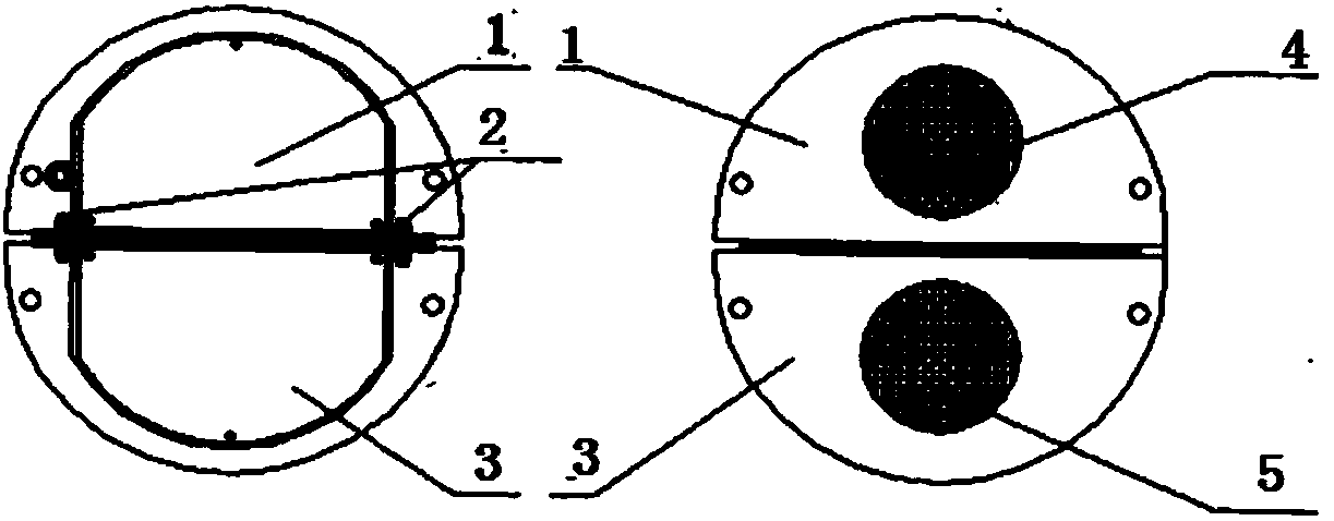
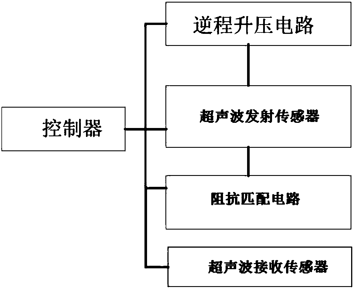
[0020] like Figure 1 to Figure 4 As shown, in this embodiment, a control system for the blind area of ​​an ultrasonic transducer includes a dual-sensor ultrasonic transducer, a controller and a reverse boost circuit; the dual-sensor ultrasonic ring energy device includes an ultrasonic transmitting sensor 4, an ultrasonic receiving sensor The sensor 5 and the ultrasonic transmitting sensor 4 are placed in the transmitting sensor shell 1, the ultrasonic receiving sensor 5 is placed in the receiving sensor shell 3, and the transmitting sensor shell 1 and the receiving sensor shell 3 are con...


PUM


Abstract

The invention discloses a control system for the blind area of ​​an ultrasonic transducer, which includes a double-sensor ultrasonic transducer, a controller and a reverse boost circuit; the double-sensor ultrasonic ring energy device includes an ultrasonic transmitting sensor, an ultrasonic receiving sensor, and an ultrasonic transmitting sensor Placed in the shell of the transmitting sensor, the ultrasonic receiving sensor is placed in the shell of the receiving sensor, and the shell of the transmitting sensor and the shell of the receiving sensor are connected together with a connecting piece; The boost circuit adjusts the driving voltage output to the ultrasonic transmitting sensor according to the reverse boost amplitude control signal; the reverse boost amplitude control signal is used to control the driving voltage of the ultrasonic transmitting sensor to change in the same direction as the distance to be measured. The invention has the advantages of small measurement blind area, wide measurement range and high detection precision.

Description

technical field [0001] The invention relates to the field of ultrasonic transducer control, in particular to a control system for the blind area of ​​the ultrasonic transducer. Background technique [0002] When using ultrasonic waves to measure the flow rate and object position, the ultrasonic transducer is excited by electric pulses to make it emit ultrasonic excitation signals. The ultrasonic signals propagate in the medium and are reflected back when they encounter different interfaces (such as the interface of water, oil and air). The returned ultrasonic signal is collectively referred to as the echo signal, and the flow or object position is measured by using the propagation time of the ultrasonic excitation signal and the ultrasonic echo signal. [0003] However, the working blind area of ​​the ultrasonic transducer is an obstacle to realize flow monitoring or position detection through ultrasonic waves. The electric pulse signal causes the energy conversion element ...

Claims


Application Information

Patent Timeline
Patent Type & Authority Applications(China)
IPC IPC(8): G01F1/66G01B17/00
CPCG01F1/66G01B17/00
Inventor 文登国蔡黎周海斌
Owner GUANGHAN SIKE XINDA TECH CO LTD
Why Eureka
Try Eureka