

Bypass parallel-connection constant-current source circuit
A technology of constant current source and bypass resistor is applied in the field of bypass parallel constant current source circuit, which can solve the problems of unsatisfactory performance and easy instability of constant current source, and achieve the effect of solving unsatisfactory performance and stable output current.
- Summary
- Abstract
- Description
- Claims
- Application Information
AI Technical Summary
Problems solved by technology
Method used
Image

Examples
Embodiment 1
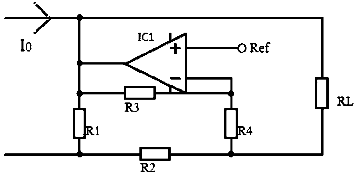
[0022] Example 1: Please refer to figure 1 As shown, a bypass parallel constant current source circuit includes a controlled constant current source and a load RL, and also includes a controllable load connected in parallel to the load RL, wherein the controllable load includes There are operational amplifier IC1, reference power supply, bypass resistor R1, and feedback unit. One end of bypass resistor R1 and one end of load RL are connected to the positive pole of the controlled constant current source, and the other end of bypass resistor R1 is connected to the controlled constant current source. The negative pole of the source is connected, the other end of the load RL is connected to the negative pole of the controlled constant current source through the sampling resistor R2, one end of the load RL is connected to the inverting input end of the operational amplifier IC1 through the feedback unit, and the output end of the operational amplifier IC1 is respectively connected...
Embodiment 2
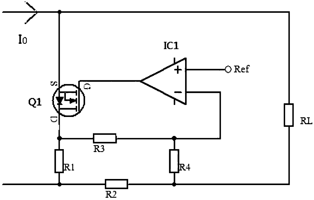
[0024] Example 2, please refer to figure 2 As shown, further, it also includes a MOS transistor Q1, the source of the MOS transistor Q1 is connected to the positive electrode of the controlled constant current source, the gate of the MOS transistor Q1 is connected to the output terminal of the operational amplifier IC1, and the MOS transistor Q1 The drain is connected to one end of the bypass resistor R1. Using the above scheme, the MOS tube is used to change the voltage to control the current characteristics, and the driving capability of the MOS tube Q1 is greater than that of the operational amplifier IC1, so that the current flowing from the MOS tube Q1 can be larger. .
[0025] The use principle of the present invention is as follows: current I0 is the total current in the circuit, current I0 is the current of the load RL plus the current flowing through the side resistor R1, and the sampling resistor R2 is used to detect the voltage flowing through the load RL and pass ...
Embodiment 3
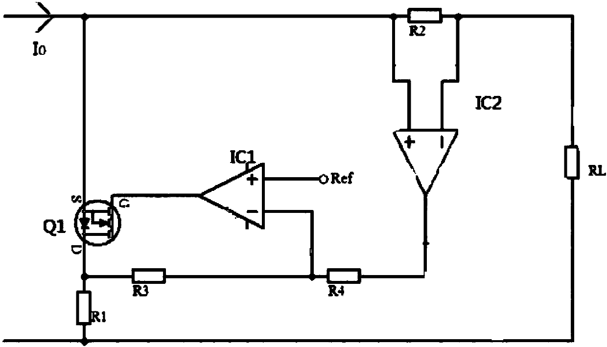
[0026] Example 3: Please refer to image 3As shown, a bypass parallel constant current source circuit includes a controlled constant current source and a load RL, and also includes a controllable load connected in parallel to the load RL, wherein the controllable load includes There are operational amplifier IC1, reference power supply, bypass resistor R1, feedback unit and operational amplifier IC2 for current detection, one end of the bypass resistor R1 is connected to the positive pole of the controlled constant current source, and the other end is connected to the controlled constant current source The negative pole of the sampling resistor R2 is connected to the positive pole of the controlled constant current source, and the other end is connected to the negative pole of the controlled constant current source through the load RL. The output terminal of the operational amplifier IC2 is connected to the inverting input terminal of the operational amplifier IC1 through the ...
PUM
 Abstract
Description
Claims
Application Information