
Video output method and system of ultrasound diagnostic equipment

A technology of video output and ultrasonic diagnosis, applied in the directions of sonic diagnosis, infrasound diagnosis, ultrasonic/sonic/infrasonic diagnosis, etc., can solve the problems of complicated wiring, bulky equipment, high cost, and achieve the effect of simplifying hardware conditions

Inactive Publication Date: 2018-03-30
VINNO TECH (SUZHOU) CO LTD
View PDF6 Cites 0 Cited by
  • Summary
  • Abstract
  • Description
  • Claims
  • Application Information

AI Technical Summary

Problems solved by technology

In recent years, in order to increase the convenience of operation, more and more medical ultrasonic diagnostic equipment began to adopt the hardware configuration of the main display screen + touch screen, but the video output method of the medical ultrasonic diagnostic system still stays on a single screen, that is, the main screen with ultrasonic images Copy output of
This makes it difficult to display the touch screen, which is mainly used for human-computer interaction, when users are teaching and demonstrating, increasing the workload of user explanations
[0003] In order to facilitate the display of touch screens for human-computer interaction, the commonly used video splicing technology in the field of video surveillance and video acquisition is usually used: use a hub or workstation to synthesize multiple video sources into a multi-screen video and display it on the output display; The video output method requires additional hardware, even a workstation, high cost, complex wiring, and bulky equipment

Method used


Image

  • Video output method and system of ultrasound diagnostic equipment
  • Video output method and system of ultrasound diagnostic equipment
  • Video output method and system of ultrasound diagnostic equipment

Examples


Embodiment Construction

[0038] The present invention will be described in detail below in conjunction with specific embodiments shown in the accompanying drawings. However, these embodiments do not limit the present invention, and any structural, method, or functional changes made by those skilled in the art according to these embodiments are included in the protection scope of the present invention.

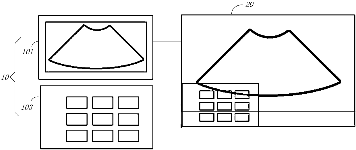
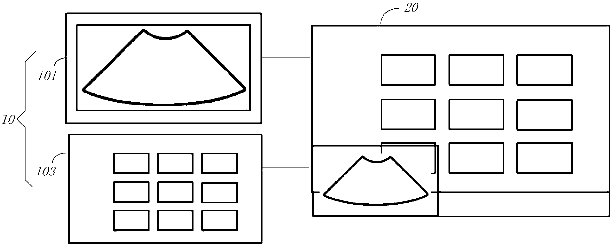
[0039] The ultrasonic diagnostic equipment used in the ultrasonic imaging process usually includes a central processing unit, a display device and a human-computer interaction input device interconnected with the central processing unit; the display device generally uses a display screen or other output methods to indicate the central processing unit. The prompt information displayed is used to display ultrasound images and corresponding reference information; the human-computer interaction input device is used to send instructions through the central processing unit, which can instruct the display devi...


PUM


Abstract

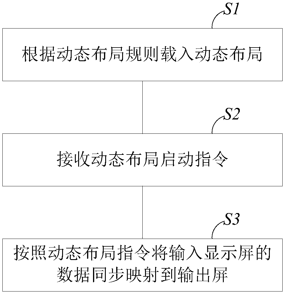
The invention provides a video output method and system of ultrasound diagnostic equipment. The method comprises the steps that according to a dynamic layout rule, a dynamic layout is loaded, whereinthe dynamic layout rule comprises settings of a background and a foreground in an output screen, the zooming mode, the docking mode and the opacity of a focus screen and the zooming mode, the dockingmode and the opacity of a non-focus screen; a dynamic layout starting instruction is received; according to the dynamic layout instruction, the data of an input display screen is synchronously mappedto the output screen, wherein the input display screen comprises a main screen body used for displaying ultrasound images, and a touch screen body used for operating the main screen body. By means ofthe video output method and system of the ultrasound diagnostic equipment, the content displayed by the double screens of the ultrasound diagnostic equipment can be dynamically stitched according to user demands so as to achieve video output, and while it is ensured that the double-screen content is completely and clearly output, the display space is fully utilized; the hardware conditions required for the video output are simplified, and the user experience is improved when the double-screen ultrasound diagnostic equipment is used as the video output for teaching and demonstrating.

Description

technical field [0001] The invention belongs to the field of medical ultrasonic diagnostic imaging, and in particular relates to a video output method and system of ultrasonic diagnostic equipment. Background technique [0002] Ultrasound imaging has become one of the most widely used clinical diagnostic tools because of its non-invasive, real-time, convenient operation, and low price. Among them, the video output of ultrasonic diagnostic equipment has always been an essential function of medical ultrasonic diagnostic equipment, and is widely used in ultrasound teaching, demonstration, data interaction and other aspects. In recent years, in order to increase the convenience of operation, more and more medical ultrasonic diagnostic equipment began to adopt the hardware configuration of the main display screen + touch screen, but the video output method of the medical ultrasonic diagnostic system still stays on a single screen, that is, the main screen with ultrasonic images ...

Claims


Application Information

Patent Timeline
Patent Type & Authority Applications(China)
IPC IPC(8): A61B8/00
CPCA61B8/461
Inventor 孙斯亮王占文贺祥
Owner VINNO TECH (SUZHOU) CO LTD
Learn More