Double-couple source ground-well transient electromagnetic detection method

A transient electromagnetic and detection method technology, which is applied in the fields of electric/magnetic exploration, geophysical measurement, radio wave measurement system, etc., can solve the problems that the field source signal strength cannot meet the large depth, small detection distance, detection requirements, etc. , to achieve the effect of ensuring detection accuracy and resolution, reducing tedious work, and improving construction efficiency

Inactive Publication Date: 2018-03-30
XIAN RES INST OF CHINA COAL TECH& ENG GROUP CORP
View PDF6 Cites 12 Cited by
  • Summary
  • Abstract
  • Description
  • Claims
  • Application Information

AI Technical Summary

Problems solved by technology

However, this technology still has the following problems: the set target is often placed in front of the detection, and the influence of the medium beyond the detection interface, especially the rear, is not ruled out; The interpretation theory needs to be perfected; the detection anomaly area is much larger than the actual geological anomaly body, and the interpretation method needs to be improved; the underground launcher is affected by the space of the underground roadway, so it cannot be made larger, because the emission magnetic moment cannot be large enough, seriously Affected the detection depth and accuracy, etc.
The disadvantages of this technology are: higher requirements on the working environment, such as no electrical equipment emitting electromagnetic waves around the worki

Method used


Image

  • Double-couple source ground-well transient electromagnetic detection method
  • Double-couple source ground-well transient electromagnetic detection method

Examples


Embodiment Construction

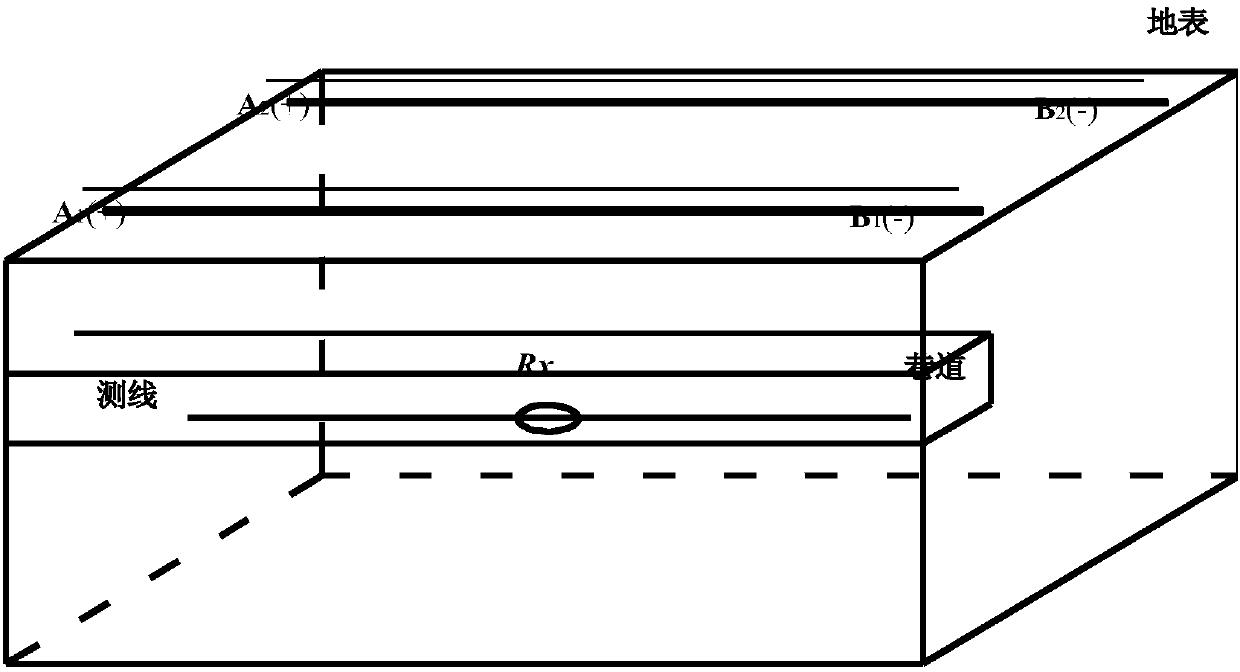
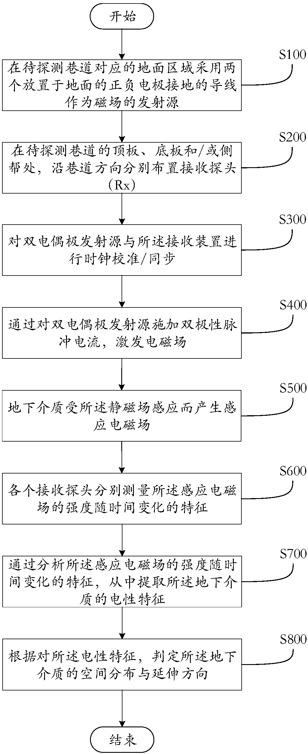
[0018] Below, the implementation of the technical solution will be further described in detail in conjunction with the accompanying drawings.

[0019] Those skilled in the art can understand that although the following description involves many technical details related to the embodiments of the present invention, this is only an example for illustrating the principle of the present invention, and does not imply any limitation. The present invention can be applied to occasions other than the technical details exemplified below, as long as they do not deviate from the principle and spirit of the present invention.

[0020] In addition, in order to avoid making the description in this manual limited to redundant, in the description in this manual, some technical details that can be obtained in the existing technical documents may be omitted, simplified, modified, etc. understandable to human beings, and this does not affect the adequacy of the disclosure of this specification. ...


PUM

PropertyMeasurementUnit
Spacingaaaaaaaaaa

Abstract

The invention relates to a double-couple source ground-well transient electromagnetic detection method, which includes the following steps: a grounding lead is placed in a ground area corresponding toa roadway to be detected which is located underground as a double-electric dipole emission source used for generating an electromagnetic field; at a top plate, a bottom plate and/or a lateral wall ofthe roadway to be detected, receiving devices are arranged along the roadway direction, and the receiving devices include single or a plurality of receiving probes, and can collect electromagnetic signals received by each of the receiving probes; bipolar pulse current is applied to the double-electric dipole emission source to excite an electromagnetic field; an underground medium is subjected toinduction of the electromagnetic field to generate an induction electromagnetic field, and the underground medium includes ground or a detection target layer/body; each of the receiving probes measures the induction electromagnetic field to obtain characteristics of the induction electromagnetic field which change with time; by analysis of the characteristics changing with time, electrical characteristics of the underground medium are extracted; and according to the electrical characteristics, the spatial distribution and extending direction of the underground medium are judged.

Description

technical field [0001] The invention belongs to the technical field of geological detection of coal mining working faces in coal mines, and relates to a ground-underground multi-source transient electromagnetic detection method for water-bearing and water-conducting geological structures affecting safe production on the top plate, bottom plate, inside of the working face and the tunneling head. Background technique [0002] There are many methods for geological detection of coal mining face in coal mines. The common ones are mine direct current method, mine transient electromagnetic method, radio wave tunnel perspective method, magnetic source ground-roadway transient electromagnetic detection method, etc. [0003] Mine direct current method is mainly used for roadway floor sounding and the water-bearing structure in front of the head, which can solve the problem of layer division and water-rich body delineation (that is, direct current sounding and advanced detection). The ...

Claims


Application Information

Patent Timeline
IPC IPC(8): G01V3/08
Inventor 韩德品李丹蒙超吴正飞石亚丁
Owner XIAN RES INST OF CHINA COAL TECH& ENG GROUP CORP
Why Eureka
Try Eureka