Sharpened front edge structure and front edge design method of transonic speed fan blade top primitive blade profile

A design method and fan blade technology, applied to pump components, mechanical equipment, components of pumping devices for elastic fluids, etc., can solve problems affecting blade stiffness, local flutter of fan blades, etc., to improve efficiency and reduce Effects of Mach number and increased stall margin

Active Publication Date: 2018-04-03
INST OF ENGINEERING THERMOPHYSICS - CHINESE ACAD OF SCI
View PDF5 Cites 1 Cited by
  • Summary
  • Abstract
  • Description
  • Claims
  • Application Information

AI Technical Summary

Problems solved by technology

[0007] In the existing advanced aviation turbofan engines, the imported fans are all transonic, and there is a strong shock wave at the top of the blade. In order to control the shock wave, the thickness of the blade tip should be smaller and smaller, and when the thickness of the blade tip is reduced to a certain extent, It will affect the stiffness of the blade, and it is easy to cause local flutter of the fan blade. In order to ensure the structural integrity of the compressor blade, the thickness of the blade tip cann

Method used


Image

  • Sharpened front edge structure and front edge design method of transonic speed fan blade top primitive blade profile
  • Sharpened front edge structure and front edge design method of transonic speed fan blade top primitive blade profile
  • Sharpened front edge structure and front edge design method of transonic speed fan blade top primitive blade profile

Examples


Example Embodiment

[0029] The present invention will be further described in detail below in conjunction with embodiments. The following embodiments are for explaining the present invention and the present invention is not limited to the following embodiments.

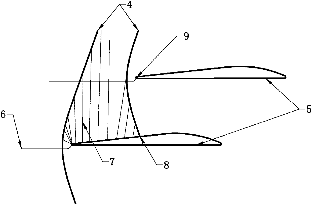
[0030] Such as Figure 4 As shown, the sharpened leading edge structure of the tip element blade shape of the transonic fan of the present invention is obtained according to the following method: First, obtain a certain length of 17 from the original front edge on the suction surface of the blade tip element shape Reference point; after that, make a straight line 19 with a certain included angle 13 with the original suction surface through this reference point; then, use a circular arc segment with a radius 14 smaller than the original leading edge radius between the straight line 19 and the original pressure surface Connected, and the other end of the straight section 19 and the original suction surface are smoothly transitioned by a radius...


PUM


Abstract

The invention relates to a front edge design method of a transonic speed fan blade top primitive blade profile. The front edge design method comprises the steps that a reference point distant from anoriginal front edge by a certain length is obtained on a suction surface of a blade top original primitive blade profile; a linear section is made by passing the reference point, wherein a certain included angle is formed between the original suction surface and the linear section; and the linear section is connected with an original pressure surface by an arc section with a small radius, the other end of the linear section is in smooth transition with the original suction surface by a chamfer, and the axial positions of a new blade front edge and an old blade front edge are kept unchanged. Since the front edge of the blade top original primitive blade profile is subjected to sharpening treatment and the effective radius of the front edge is reduced, shock wave detachment may be delayed, and the surge-to-stall margin of a fan can be improved advantageously. In addition, with the introduction of a sharpening structure, an expansion wave at the blade front edge is split into two parts, wherein one part is an expansion wave triggered by the front edge radius and the other part is an expansion wave triggered by the transition part of the linear section and the suction surface, so thatthe mach number before a channel shock wave can be lowered advantageously, and the efficiency of the blade top original primitive blade profile is improved.

Description

technical field [0001] The invention belongs to the field of transonic fan blades, and relates to a blade structure and a design method of a transonic fan, and in particular to a blade-top basic element blade shape sharpening leading edge structure and a design method of a transonic fan Background technique [0002] In contemporary advanced aviation turbofan engines, such as figure 1 As shown, the fan 1 of the transonic fan rotor is developing towards the direction of high flow capacity, high efficiency and high stability. Due to the need to take into account the working ability of the coaxial low-pressure turbine, the low-pressure shaft speed has to be selected at a higher speed. The gas flow at the top 2 of the fan blade is caused to be in a supersonic state, and a shock wave is generated at the top of the fan blade. The shock wave first has a certain supercharging effect, which can effectively improve the supercharging effect of the blade tip. However, the shock wave wil...

Claims


Application Information

Patent Timeline
IPC IPC(8): F04D29/26F04D29/66
CPCF04D29/26F04D29/666F04D29/667F05D2220/36F05D2240/302F05D2240/303
Inventor 赵胜丰阳诚武韩戈卢新根李紫良张燕峰朱俊强
Owner INST OF ENGINEERING THERMOPHYSICS - CHINESE ACAD OF SCI
Why Eureka
Try Eureka