
Elastic speed reducer

A reducer and elastic technology, which is applied in the field of elastic reducers, can solve the problems of large reducers, insufficient rigidity, and large rotational inertia, so as to ensure the center output, eliminate radial assembly errors and parts processing errors, and improve precision. Effect

Inactive Publication Date: 2018-04-03
惠州恒星智达机器人有限公司
View PDF0 Cites 0 Cited by
  • Summary
  • Abstract
  • Description
  • Claims
  • Application Information

AI Technical Summary

Problems solved by technology

Solving many problems of traditional reducers such as large body, low precision, insufficient rigidity, and large rotational inertia has become a common problem in the field of transmission technology in my country that urgently needs to be broken through

Method used


Image

  • Elastic speed reducer
  • Elastic speed reducer
  • Elastic speed reducer

Examples


Embodiment 1

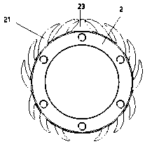
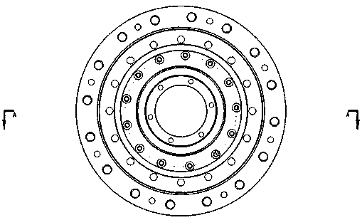
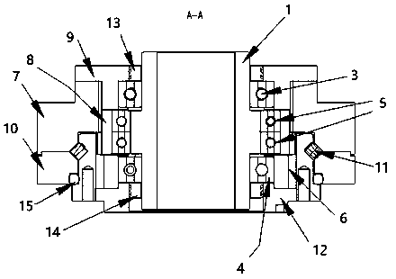
[0046] Such as figure 1 , 2 , 3, this embodiment discloses an elastic reducer, including a power input assembly, the power input assembly includes an input shaft 1, an elastic assembly arranged on the input shaft 1, and the elastic assembly is an extrusion-type deformation The extrusion-type deformation ring includes an annular ring body 2, and an elastic structural member is provided on the outer ring wall of the annular ring body.

[0047] In this embodiment, the above-mentioned elastic structure includes two shrapnel groups symmetrical to each other, and each shrapnel group includes a number of first shrapnel groups and second shrapnel groups distributed on the outer ring wall of the annular ring, and the outer ring of the ring ring The wall is provided with an elastic limit boss 23, the first shrapnel group and the outer ring wall of the annular ring form an angle that is biased toward the elastic limit boss, and the second shrapnel group forms an opposite angle to the ou...

Embodiment 2

[0075] refer to figure 1 , 2 , this embodiment is similar to Embodiment 1, disclosing an elastic reducer, including a power input assembly, the power input assembly includes an input shaft 1, an elastic assembly arranged on the input shaft 1, and the elastic assembly is an extrusion One of the differences from Embodiment 1 is that the inner ring wall of the annular ring body is provided with an elastic structural member.

[0076] In this embodiment, the above-mentioned elastic structure includes two shrapnel groups that are symmetrical to each other, and each shrapnel group includes a number of first shrapnel groupings and second shrapnel groupings distributed on the inner wall of the annular ring. There is an elastic limit boss, the first shrapnel group and the ring wall inside the annular ring form an angle that is biased towards the elastic limit boss, and the second shrapnel group and the inner ring wall of the annular ring form a reverse elastic limit boss angle. Each ...


PUM


Abstract

The invention provides an elastic speed reducer. The elastic speed reducer includes a power input assembly, the power input assembly includes an input shaft, and an elastic assembly arranged on the input shaft; the elastic assembly is one or more extrusion-type deformation rings, and the extrusion-type deformation ring includes An annular ring body, the outer ring wall and / or the inner ring wall of the annular ring body are provided with elastic structural members. The elastic structure body includes two mutually symmetrical shrapnel groups, each shrapnel group includes several The first shrapnel grouping and the second shrapnel grouping of the outer ring wall or the inner ring wall, the outer ring wall or the inner ring wall of the annular ring is provided with an elastic limit boss, the first shrapnel grouping and the outer ring of the annular ring The wall or the inner ring wall forms an included angle biased towards the elastic limiting boss, and the second shrapnel group forms an included angle opposite to the elastic limiting boss with the outer ring wall or the inner ring wall of the annular ring.

Description

technical field [0001] The invention relates to the technical field of elastic reducers, in particular to elastic reducers. Background technique [0002] The deceleration mechanism is widely used in high-load and high-precision industries such as robots and automobiles. As a key mechanical transmission component, the deceleration mechanism is crucial to the performance of robots, automobiles and other products. In particular, the robot industry is developing rapidly, and the market's enthusiasm for more precise, lightweight, and intelligent robots has also put forward higher requirements for the deceleration mechanism that realizes the fine movements of robot joints. [0003] The existing reducer mainly realizes transmission through gears, worm gears or sprocket chains. The commonly used reducers on the market mainly include needle-toothed cycloid reducers and harmonic reducers. However, no matter the pin-toothed cycloid reducer or the harmonic reducer, there are theoretic...

Claims


Application Information

Patent Timeline
Patent Type & Authority Applications(China)
IPC IPC(8): F16F1/34F16H49/00F16H57/021F16H57/023
CPCF16H49/001F16F1/34F16H57/021F16H57/023
Inventor 李勇强
Owner 惠州恒星智达机器人有限公司
Learn More