Illumination system for X-ray machine and laser projection equipment

A lighting system, lighting beam technology, applied in optics, optical components, installation and other directions to achieve the effect of improving the uniform light effect and improving the uniform light effect

Active Publication Date: 2018-04-03
HISENSE
View PDF3 Cites 3 Cited by
  • Summary
  • Abstract
  • Description
  • Claims
  • Application Information

AI Technical Summary

Problems solved by technology

[0005] The invention provides an optical-mechanical lighting system, which solves the technical problem of both

Method used


Image

  • Illumination system for X-ray machine and laser projection equipment
  • Illumination system for X-ray machine and laser projection equipment
  • Illumination system for X-ray machine and laser projection equipment

Examples


Embodiment Construction

[0021] In order to make the purpose, technical solutions and advantages of the present invention clearer, the present invention will be further described in detail below in conjunction with the accompanying drawings. Obviously, the described embodiments are only some of the embodiments of the present invention, rather than all of them. Based on the embodiments of the present invention, all other embodiments obtained by persons of ordinary skill in the art without making creative efforts belong to the protection scope of the present invention.

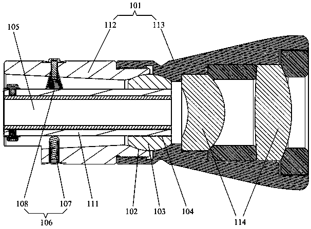
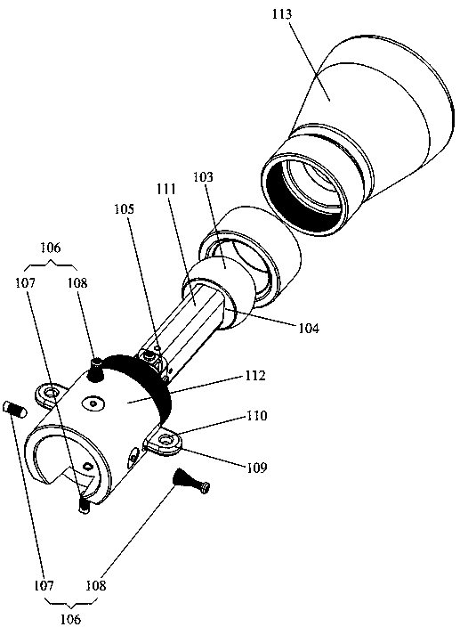
[0022] Please refer to figure 2 , an embodiment of the present invention provides an optomechanical lighting system, including: a tube body 101 , the tube body 101 , a light guide 105 and a lens group 114 . Wherein, the tube body 101 includes a first housing 112 and a second housing 113, one or both ends of the light guide 105 are disposed in the first housing 112, and part or all of the lenses of the lens group 114 are disposed in the...


PUM


Abstract

The invention provides an illumination system for an X-ray machine and laser projection equipment, and the system comprises a light guide tube, a lens group, and a tube body, wherein the interior of the tube body is provided with a ball socket. The system also comprises a sphere which is provided with a connection through hole, is disposed in the ball socket and makes contact with the spherical surface of the ball socket, wherein there is a spherical rotation freedom degree between the sphere and the ball socket. The light guide tube is disposed in the connection through hole, and is fixedly connected with the sphere. The system also comprises an adjustment system, and the adjustment system comprises a telescoping device and an elastic part, which are arranged to be opposite to each otherin the same direction. The telescoping device and the elastic part are disposed on the tube body in the radial direction of the tube body. On the one hand, an adjustment structure can be used for adjusting the position of the light guide tube, and improves the light uniformizing effect; on the other hand, one end of a first housing and one end of a second housing are used for forming a ball socketstructure, thereby enabling the connection relation between the first housing and the second housing to remain unchanged even during the adjustment of the light guide tube, and guaranteeing the stability of position connection of a relative structure of the light guide tube and the lens group.

Description

technical field [0001] The invention relates to the field of projection equipment, in particular to an optical-mechanical lighting system and laser projection equipment. Background technique [0002] In DLP (Digtal Light Processing, digital light processing) projection, DMD (Digtal Micromirror Device, digital micromirror device) is the core device in the optical machine, which is used to pass the illumination beam output by the front-end illumination system through tens of millions of tiny mirrors. Reflected into the projection lens imaging. Among them, the front-end lighting system receives the light beam emitted by the projection light source. During product design, the light source and the light-mechanical part are usually designed separately and then assembled. The lighting system of an optical machine usually includes a uniform light component and a lens group. The light uniform component can be a light guide or a fly eye lens. The lens group is usually a converging le...

Claims


Application Information

Patent Timeline
IPC IPC(8): G03B21/20G02B7/24
CPCG02B7/24G03B21/20
Inventor 鲁文生
Owner HISENSE
Why Eureka
Try Eureka