Limb prothesis control method and device and storage medium
A control method and prosthetic technology, applied in the field of medical devices, can solve problems such as short use time, danger, and external force assistance for passive prosthetic wearers
- Summary
- Abstract
- Description
- Claims
- Application Information
AI Technical Summary
Problems solved by technology
Method used
Image

Examples
no. 1 example
[0027] Traditional lower limb prostheses are mainly passive prostheses, which rely on the swing of the residual limb to drive the movement of the prosthesis during walking to achieve alternate walking, and the user consumes a lot of energy. However, purely active prosthetics generally use motors as the actuators to drive joint flexion and extension movements. Since the motors need to run continuously during the joint movement process, and require a large driving force when standing up, going up and down stairs, etc., the power consumption is extremely high. The problem of power supply has become a bottleneck that is difficult to break through at present. Therefore, the lower limb prosthesis with active and passive hybrid drive has become a new research direction at home and abroad. How to set the active control mode and passive control mode, and how to judge when to use which control mode is a key problem that needs to be solved. The problem of type identification. In order t...
no. 2 example
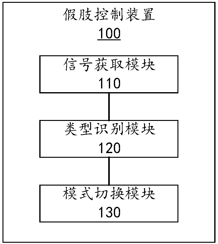
[0043] In order to realize the above information processing method, the second embodiment of the present invention provides a prosthesis control device 100 . Please refer to figure 2 , figure 2 It is a block diagram of a prosthetic control device provided by the second embodiment of the present invention. The prosthesis control device 100 includes a signal acquisition module 110 , a type identification module 120 and a mode switching module 130 .
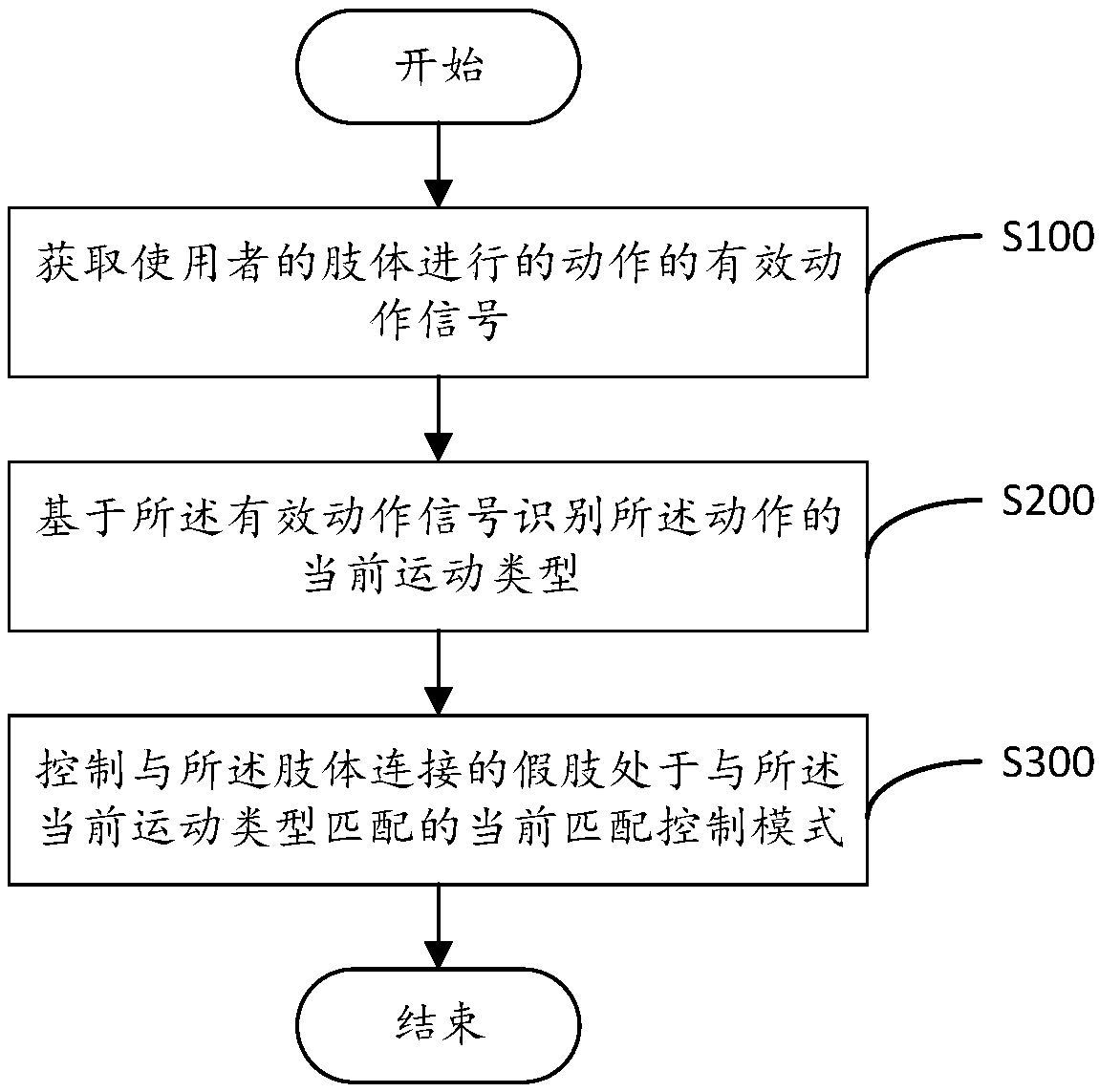
[0044] The signal acquisition module 110 is configured to acquire effective motion signals of motions performed by the user's limbs, and is also configured to obtain current motion signals of motions performed by the user's limbs.
[0045] A type identifying module 120, configured to identify the current motion type of the action based on the effective action signal.
[0046] A mode switching module 130, configured to control the prosthesis connected to the limb to be in a current matching control mode matching the current move...
PUM
 Abstract
Description
Claims
Application Information
PatSnap Eureka turns technology decisions into work you can execute. Powered by our Innovation Knowledge Graph, it runs expert workflows across engineering, life sciences, materials and intellectual property. Get your review-ready output in minutes.


