Variable-rigidity part suction device and plate suction bending method

A technology of suction device and variable stiffness, which is applied in the direction of feeding device, positioning device, storage device, etc., can solve the problems of slow speed, large volume, and inability to arrange suction cups when picking up and releasing parts, so as to achieve automation efficiency. High, small size, fast absorption effect

Active Publication Date: 2018-04-06
NANJING UNIV OF POSTS & TELECOMM
View PDF7 Cites 3 Cited by
  • Summary
  • Abstract
  • Description
  • Claims
  • Application Information

AI Technical Summary

Problems solved by technology

[0010] 1. The volume is too large, especially when bending small parts or opening holes in small parts, it is completely inoperable, and the position of the suction cup cannot be arranged.
[0011] 2. The vacuum chuck and the electromagnet work independently, and th

Method used


Image

  • Variable-rigidity part suction device and plate suction bending method
  • Variable-rigidity part suction device and plate suction bending method
  • Variable-rigidity part suction device and plate suction bending method

Examples


Embodiment Construction

[0045] The present invention will be further described in detail below in conjunction with the accompanying drawings and specific preferred embodiments.

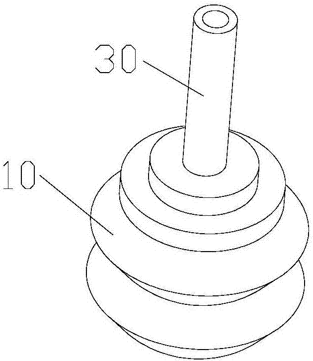
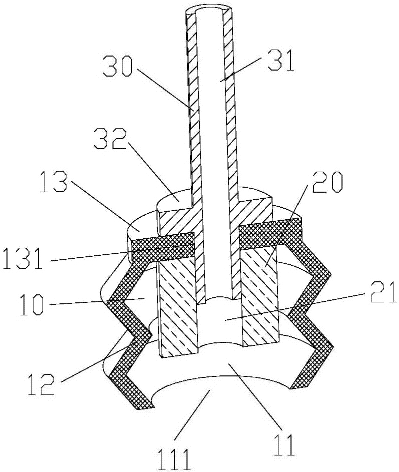
[0046] Such as figure 1 with figure 2 As shown, a variable stiffness part suction device includes a flexible organ cavity 10, an electromagnet 20, a connecting rod 30 and a vacuum pump.

[0047] The flexible organ cavity is mainly formed by the ring-shaped suction cup 11, the flexible telescopic side wall 12 and the top surface 13. Furthermore, the ring-shaped suction cup, the flexible telescopic side wall and the top surface are preferably integrated.

[0048] The annular suction cup is arranged at the bottom of the flexible telescopic side wall, and the center of the annular suction cup is provided with a suction cup central hole 111 .

[0049] The top surface is arranged on the top of the flexible telescopic side wall, and the center of the top surface is provided with a top surface central hole 131 .

[0050] The ele...


PUM


Abstract

The invention discloses a variable-rigidity part suction device and a plate suction bending method. The plate suction bending method includes the steps that firstly, plate rigid suction and positioning are conducted; secondly, plate transferring is conducted; thirdly, plate flexible suction is conducted; and fourthly, bending and deviation compensation are conducted. The part suction device comprises a flexible organ cavity, an electromagnet, a connecting rod and a vacuum pump. The flexible organ cavity comprises an annular sucker, a flexible telescopic side wall and a top plate, and the flexible organ cavity is defined by the annular sucker, the flexible telescopic side wall and the top face. The electromagnet is arranged in the flexible organ cavity. One end of the connecting rod is connected with a robot wrist, and the other end of the connecting rod stretches in the flexible organ cavity from a center hole in the top face and is fixedly connected with the electromagnet. By means ofthe variable-rigidity part suction device and the plate suction bending method, the vacuum sucker and the electromagnet are ingeniously and organically combined, on one hand, the size is small and can be suitable for bending machining of small parts or trepanning of small parts or the like; and on the other hand, the suction speed is high, and the automation efficiency is high.

Description

technical field [0001] The invention relates to an auxiliary device and a method in a sheet metal processing production line, in particular to a device for absorbing parts with variable stiffness and a method for absorbing and bending plates. Background technique [0002] The parts suction device is connected to the end of the robot for grabbing and handling the parts. [0003] At present, there are mainly two methods for picking up parts: [0004] 1. Use vacuum suction cup to absorb [0005] On the one hand, due to the slow speed of sucking and releasing parts, according to actual experience, it usually takes about 1-2 seconds to suck and release parts, which has an impact on the production efficiency of the automated production line. ,low efficiency. On the other hand, the vacuum chuck is a flexible part, and there is elastic deformation when the part is positioned, which affects the accuracy. [0006] 2. Using electromagnet to absorb [0007] Although the electromagn...

Claims


Application Information

Patent Timeline
IPC IPC(8): B21D43/18B21D43/00B21D5/01B21D5/04B25J15/06
CPCB21D5/002B21D5/01B21D5/04B21D43/18B25J15/0608B25J15/0625
Inventor 徐丰羽李剑蒋国平
Owner NANJING UNIV OF POSTS & TELECOMM
Why Eureka
Try Eureka