All-terrain part conveying robot

A handling robot and all-terrain technology, which is applied in the direction of manipulators, manufacturing tools, etc., to achieve the effect of realizing automatic handling and reducing the occupied space

Active Publication Date: 2018-04-06
ZHENJIANG VOCATIONAL TECHN COLLEGE
View PDF5 Cites 0 Cited by
  • Summary
  • Abstract
  • Description
  • Claims
  • Application Information

AI Technical Summary

Problems solved by technology

[0002] With the rapid development of artificial intelligence technology, the application of robots in the machinery industry is becoming more and more extensive. The traditional way of manipulating the handling trolley to carry parts can no longer meet the modern industry's pursuit of low cost and high efficiency. The all-terrain handling method of manual handling requires the development of a multifunctional all-terrain parts handling robot

Method used


Image

  • All-terrain part conveying robot
  • All-terrain part conveying robot
  • All-terrain part conveying robot

Examples


Embodiment 1

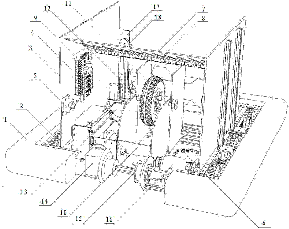
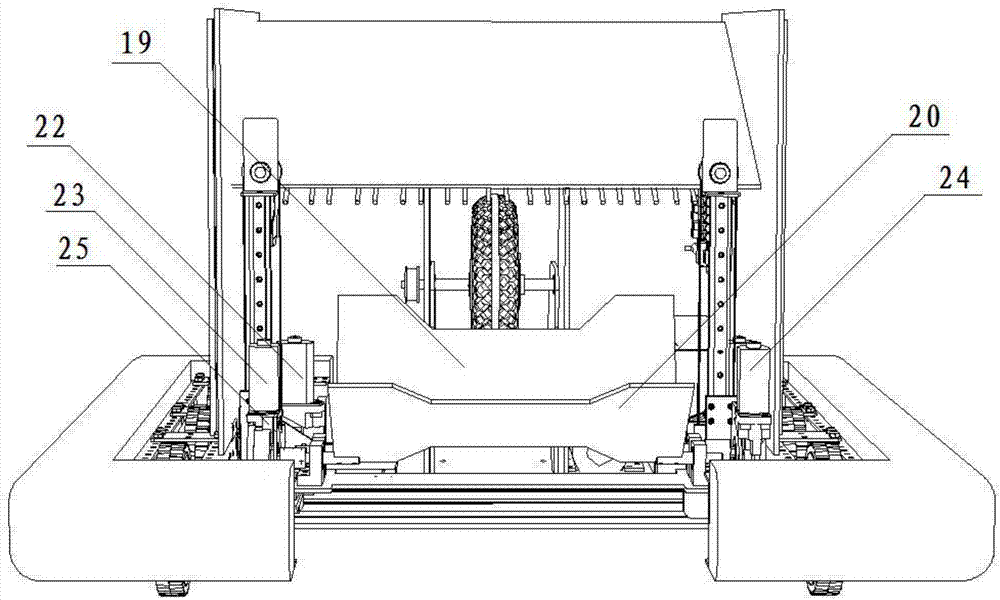
[0034] Embodiment 1, the present invention is used to carry ball parts, such as fuel balls, plastic balls, etc., the main controller 6 controls the roller drive motor 16 to drive the rollers 2 to move, through the rear baffle 19 on the pick-up mechanism and the front baffle 20 The relative rotation adjusts the size of the charging trough formed with the carrier plate 21, and then the tailgate rotating motor 22 guides the ball parts into the arc track plate 10 of the launch mechanism by adjusting the rotation of the tailgate 19, and the main controller 6 The rotating speed of driving the ball parts is obtained by controlling the flywheel drive motor 13 to drive the flywheel 11 to rotate in advance, so as to launch the ball parts along the arc track plate 10 into a predetermined collection device.

Embodiment 2

[0035] Embodiment 2, the present invention is used for handling gear parts, main controller 6 controls the first lifting motor 23 and the second lifting motor 24 to drive the synchronous belt 18 to lift along the guide rail, and realize the bearing plate 21 and the rear baffle 19, the front baffle The lifting of the charging trough formed by 20 hangs the gear parts in the collection device, and the roller drive motor 16 pre-drives the roller 2 to move and cooperate with the rotation of the front fender 20 and the rear fender 19 to realize picking up the gear parts.

Embodiment 3

[0036]Embodiment 3, the present invention hinges the rope to be climbed through the helical mechanism 15 on the rope climbing mechanism, and drives the helical mechanism 15 to rotate and wrap the rope through the helical drive motor 14 to drive the whole robot to climb along the rope.

[0037] The present invention can communicate with the router 5 through a wireless network or a cable to communicate with the router 5 through an external control computer. The instrument sensor and the ultrasonic sensor are respectively used to correct the movement angle of the robot and to precisely control the distance between the robot and the target.


PUM


Abstract

The invention discloses an all-terrain part conveying robot. The all-terrain part conveying robot comprises a main body support and a plurality of rollers, wherein the rollers are fixed on the edge ofthe inner side of the main body support; a power distribution panel, a router and a main controller are arranged on the main body support; a rope climbing mechanism is fixedly arranged on the front part of the main body support; an emission mechanism is fixedly arranged on the middle part of the main body support; a picking-up mechanism is fixedly arranged on the rear part of the main body support; the output end of the main controller is separately connected with the input end of the rope-climbing mechanism, the input end of the emission mechanism and the input end of the picking-up mechanism; the power distribution panel is separately electrically connected with the router and the main controller; and the input-output ends of the router are connected with the input-output ends of the main controller. According to the all-terrain part conveying robot, the emission mechanism, the picking-up mechanism and the rope-climbing mechanism are set through the main controller, so that all-terrain conveying for spherical parts and gear parts is realized.

Description

technical field [0001] The invention relates to an all-terrain parts handling robot, which belongs to the technical field of robot application. Background technique [0002] With the rapid development of artificial intelligence technology, the application of robots in the machinery industry is becoming more and more extensive. The traditional way of manipulating the handling trolley to carry parts can no longer meet the modern industry's pursuit of low cost and high efficiency. The all-terrain handling method of manual handling requires the development of a multifunctional all-terrain parts handling robot. Contents of the invention [0003] The purpose of the present invention is to overcome the defects in the prior art, solve the above technical problems, and propose an all-terrain parts handling robot. [0004] The present invention adopts the following technical scheme: an all-terrain parts handling robot, which is characterized in that it includes a main body bracket ...

Claims


Application Information

Patent Timeline
Patent Type & Authority Applications(China)
IPC IPC(8): B25J5/00B25J13/08B25J19/00B25J11/00
CPCB25J5/007B25J11/00B25J13/088B25J19/00Y02T10/70
Inventor 施琴党丽峰史银花左文艳
Owner ZHENJIANG VOCATIONAL TECHN COLLEGE
Why Eureka
Try Eureka