Mechanical arm

A manipulator and plane technology, applied in the field of manipulators, can solve the problems of bump damage on the piston rod surface, low efficiency of small blanking, high labor cost, etc., and achieve the effect of avoiding bump damage, high labor cost and high labor intensity

Inactive Publication Date: 2018-04-06
宁波旺潮轴业有限公司
View PDF5 Cites 5 Cited by
  • Summary
  • Abstract
  • Description
  • Claims
  • Application Information

AI Technical Summary

Problems solved by technology

[0002] The piston rod is a key component that plays an important role in the shock absorber. There are many processing procedures for the piston rod, including the quenching process. The quenching must be completed on the matching CNC quenching machine tool. It is done manually, the efficiency of small blanking is low, and it will cause bump damage on the surface of the piston rod, one person, one machine, high labor cost, high labor intensity, and a little carelessness will cause burns, which needs further improvement

Method used


Image

  • Mechanical arm
  • Mechanical arm

Examples


Embodiment Construction

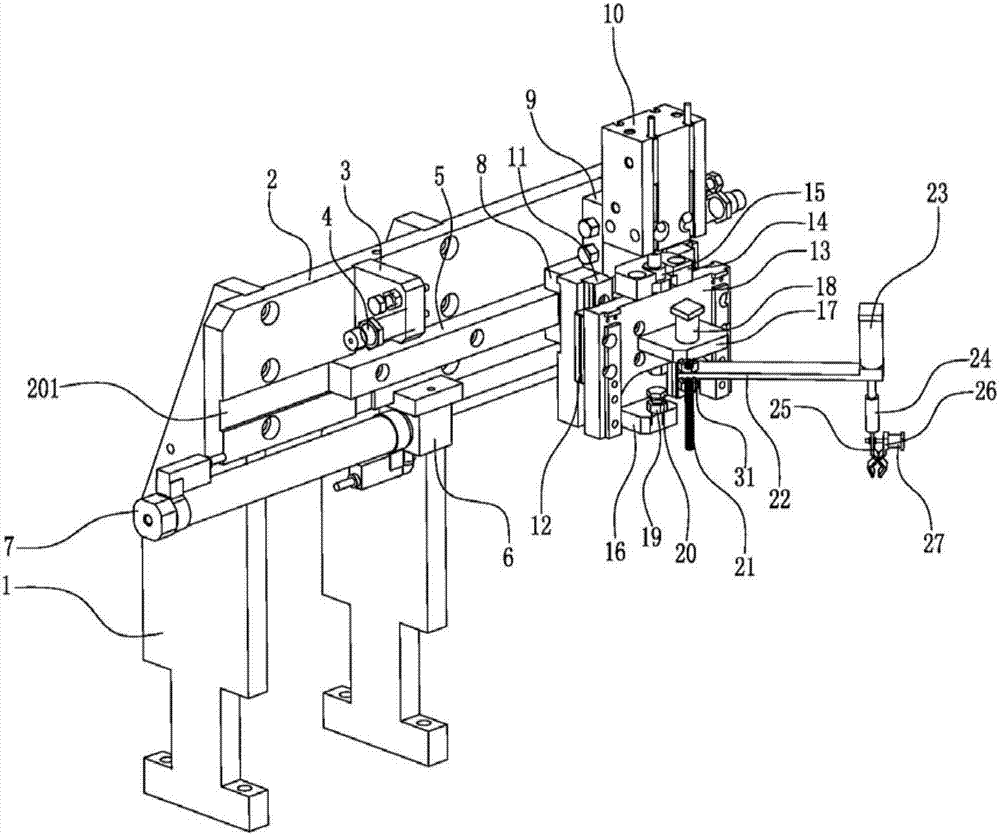
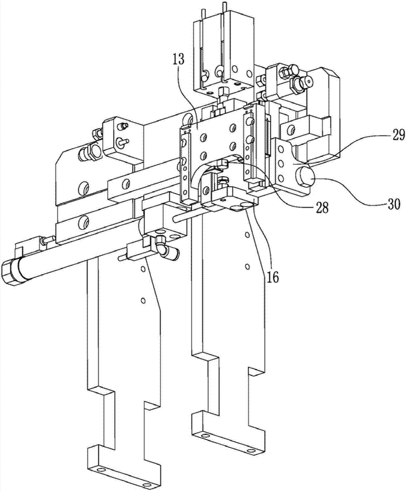
[0015] Such as Figure 1~2 As shown, a manipulator includes a support block 1, a back plate 2, an extension block 3, a buffer 4, a first guide rail 5, a positioning block 6, a first cylinder 7, a first slider 8, a side block 29, and a shaft sleeve 30. Lifting assembly and swing arm assembly; two support blocks 1 distributed parallel to each other are fixed on the back plane of the back plate 2; the lower ends of the two support blocks 1 are fixed at the designated position of the machine tool; the front side of the back plate 2 There are positioning grooves 201 distributed horizontally and horizontally on the plane, the first guide rail 5 is embedded and fixed in the positioning groove 201, and the first slider 8 is sleeved and connected to the outside of the first guide rail 5; the front side plane of the back plate 2 is fixed with The extension block 3, the extension block 3 is located above the first guide rail 5, the buffer 4 distributed horizontally and horizontally is em...


PUM


Abstract

The invention relates to a mechanical arm. The mechanical arm comprises supporting blocks, a back plate, an extending block, a buffer, a first guide rail, a positioning block, a first air cylinder, afirst sliding block, a side block, a shaft sleeve, a lifting component and a swing arm component. Automatic feeding and discharging can be achieved on a numerical control quenching machine tool, the operation is simple and convenient, collision and damage of the surface of a piston rod are avoided, the feeding and discharging efficiency is greatly improved, one person can manage multiple machines,the labor cost and the labor intensity are reduced, and the personal safety of operators is guaranteed.

Description

technical field [0001] The invention relates to the field of machine tool automation equipment, in particular to a manipulator. Background technique [0002] The piston rod is a key component that plays an important role in the shock absorber. There are many processing procedures for the piston rod, including the quenching process. The quenching must be completed on the matching CNC quenching machine tool. It is done manually, the efficiency of small blanking is low, and it will cause bump damage on the surface of the piston rod, one person, one machine, high labor cost, high labor intensity, and a little carelessness will cause burns, which needs further improvement. Contents of the invention [0003] In view of the present situation of the above-mentioned prior art, the technical problem to be solved by the present invention is to provide a kind of automatic loading and unloading operation on the CNC quenching machine tool, which is simple and convenient to operate, avoi...

Claims


Application Information

Patent Timeline
Patent Type & Authority Applications(China)
IPC IPC(8): B25J11/00B25J19/00C21D1/62C21D9/00
CPCB25J11/00B25J19/0091C21D1/62C21D9/0018
Inventor 张仲朝李建军
Owner 宁波旺潮轴业有限公司
Why Eureka
Try Eureka