Energy-saving water supply system for office factory building of enterprise

A water supply system and energy-saving technology, applied in water supply pipeline systems, water supply devices, water supply devices, etc., can solve the problems of wasting electric energy, large water consumption, affecting production, etc., to reduce operating costs, improve utilization, and save water sources. Effect

Active Publication Date: 2018-04-06
CHINA TOBACCO HENAN IND
View PDF4 Cites 0 Cited by
  • Summary
  • Abstract
  • Description
  • Claims
  • Application Information

AI Technical Summary

Problems solved by technology

[0002] Industrial enterprises need to use tap water to supply water for production, office, watering flowers, flushing toilets, etc. Smaller enterprises can directly use the pressure water supply of municipal tap water to meet the water demand of the whole plant, but for many larger enterprises, the water consumption Larger, due to insufficient pressure of municipal tap water, often cannot meet the needs
Therefore, it is necessary to build a water storage tank by ourselves, and then use the feed pump to pressurize the water in the storage tank to supply water for production, office work, watering flowers, flushing toilets, etc. in the whole plant. This kind of water supply system often works independently and needs to work and run all the time. In order to meet the water supply needs of the whole plant, long-term operation not only wastes electric energy, but also the water pump is prone to failure and high maintenance costs. At the same time, if there is a water leak somewhere that needs to be repaired, the whole plant needs to stop water, which will seriously affect production.

Method used


Image

  • Energy-saving water supply system for office factory building of enterprise
  • Energy-saving water supply system for office factory building of enterprise

Examples


specific Embodiment approach 1

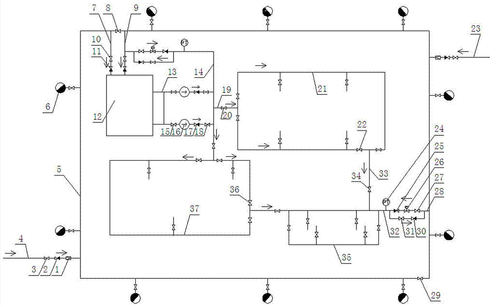
[0016] Specific implementation manner one: such as figure 1 As shown, an energy-saving water supply system for corporate office buildings includes a storage tank 12 and a main ring pipe 5 arranged along the main ring road. The main ring pipe 5 is sequentially provided with a first water inlet pipe 4 and a first valve 8. The second inlet pipe 23 and the second valve 29. The first inlet pipe 4 and the second inlet pipe 23 are both connected to the municipal water supply system. The first inlet pipe 4 and the second inlet pipe 23 are arranged diagonally, The first water inlet pipe 4 and the second water inlet pipe 23 are provided with a first valve 3, a first check valve 2 and a flow meter 1 in sequence along the water inlet direction. The main ring pipe 5 is provided with fire protection at corresponding positions. Bolt 6, a third water inlet pipe 7 and a fourth water inlet pipe 9 are provided between the reservoir 12 and the main annular pipe 5. The third water inlet pipe 7 and t...

specific Embodiment approach 2

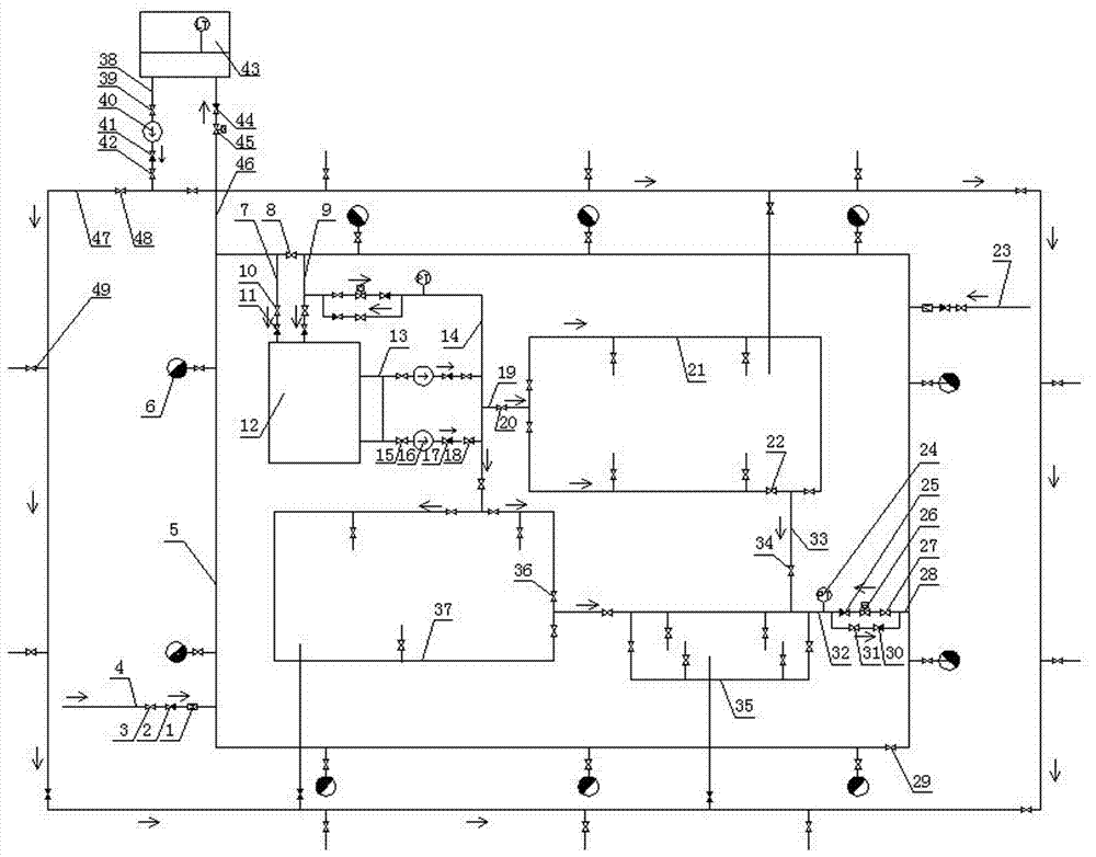
[0021] Specific implementation manner two: such as figure 2 As shown, the water supply system described in the first embodiment further includes a reclaimed water station 43. The mild sewage generated by each factory and office building flows into the reclaimed water station 43 through sewers or laying pipes (not shown in the figure). Between the reclaimed water station 43 and the main loop pipe 5, there is a clear water pipe 46 for supplying water to the reclaimed water station 43. On the clear water pipe 46, an electric valve 45 and a sixth check valve 44 are installed in sequence along the inflow direction of the clear water. A water pipe 38 is provided on the reclaimed water station 43. A ninth valve 39, a water pump 40, a seventh check valve 41, and a tenth valve 42 are installed on the water pipe 38 along the direction of water discharge. In the ring tube 47, a plurality of eleventh valves 48 are evenly installed on the auxiliary ring tube 47, and the auxiliary ring tube...


PUM


Abstract

The invention discloses an energy-saving water supply system for an office factory building of an enterprise. The energy-saving water supply system includes a water storage tank and a main annular pipe arranged along a main annular road. A first water inlet pipe, a first valve, a second water inlet pipe and a second valve are arranged on the main annular pipe in sequence. The first water inlet pipe and the second water inlet pipe are communicated with a municipal water supply system. The first valve, a first check valve and a flowmeter are sequentially arranged on the first water inlet pipe and the second water inlet pipe in the water inlet direction. A fire hydrant is disposed at the corresponding position of the main annular pipe. A third water inlet pipe and a fourth water inlet pipe are arranged between the water storage tank and the main annular pipe. The third water inlet pipe and the fourth water inlet pipe are located on the two sides of the first valve or the second valve respectively. The second valve and a second check valve are sequentially disposed on the third water inlet pipe and the fourth water inlet pipe in the water inlet direction. The overhauling of different sections of the main annular pipe is achieved, and a function of feeding water to the water storage tank 12 by the municipal water supply system is not affected in the overhauling process.

Description

Technical field [0001] The present invention relates to the technical field of water supply systems, in particular to an energy-saving water supply system for enterprise office buildings. Background technique [0002] Industrial enterprises need to use tap water to supply water for production, office, flower watering, toilet flushing, etc. Smaller enterprises can directly use municipal tap water to supply water under pressure to meet the water demand of the whole plant, but for many larger enterprises, water consumption Larger, due to insufficient municipal tap water pressure, it is often unable to meet the needs. Therefore, it is necessary to build a storage tank by itself, and then pressurize the water in the storage tank to supply water for production, office, flower watering, and toilet flushing in the whole factory through a water supply pump. This water supply system often works independently and needs to work all the time. In order to meet the water supply needs of the wh...

Claims


Application Information

Patent Timeline
Patent Type & Authority Applications(China)
IPC IPC(8): E03B1/04E03B7/04E03B7/07
CPCE03B1/04E03B1/041E03B7/04E03B7/07E03B7/072E03B7/075E03B7/077E03B2001/045
Inventor 王正伟孙中超孙琳褚东发宋志刚曹利红梁白月王虎一
Owner CHINA TOBACCO HENAN IND
Why Eureka
Try Eureka