Pressure-resistant packer

A packer and pressure technology, applied in sealing/isolation, wellbore/well parts, earthwork drilling and production, etc., can solve problems such as high protection requirements, formation pollution, cumbersome operation, etc., to avoid cumbersome operation and support Good, simple and convenient operation

Pending Publication Date: 2018-04-06
DAQING TIANDEZHONG PETROLEUM SCI & TECH CO LTD
View PDF1 Cites 3 Cited by
  • Summary
  • Abstract
  • Description
  • Claims
  • Application Information

AI Technical Summary

Problems solved by technology

[0002] Packers are divided into rotating seat packers and non-rotating seat packers, of which non-rotating seat packers include mechanical packers that are raised and lowered and various types of hydraulic packers. The lifting and lowering mechanical packer uses the lifting and lowering of the pipe string to control the sealing and unsealing of the packer. After searching, the Chinese patent authorization number is CN201710238504.0, which discloses a deep water packer device , including an upper joint, a central tube, a lower joint, slips, rubber pads, sliding sleeves and lock sleeves. The top end of the central tube is threaded with an upper joint; the bottom end of the central tube is threaded with a lower joint. Slips are installed through the upper vertebral body, and the center pipe below the upper vertebral body is fitted with sliding sleeves and locking sleeves. The existing packers have the disadvantages of cumbersome operation and long time consumption, while hydraulic packers often Due to the disconnection of the hydraulic oil circuit due to harsh environmental factors, the packer is unsealed in advance. Offshore deepwater oil and gas wells have high requirements for formation protection, and early unseal often leads to serious formation pollution.

Method used


Image

  • Pressure-resistant packer
  • Pressure-resistant packer
  • Pressure-resistant packer

Examples


Embodiment Construction

[0019] The following will clearly and completely describe the technical solutions in the embodiments of the present invention with reference to the accompanying drawings in the embodiments of the present invention. Obviously, the described embodiments are only some, not all, embodiments of the present invention.

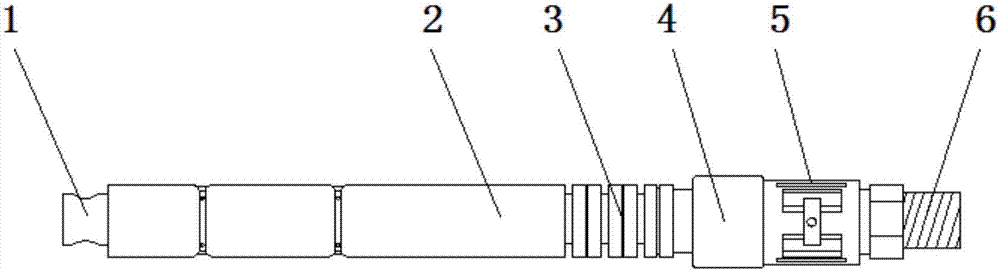
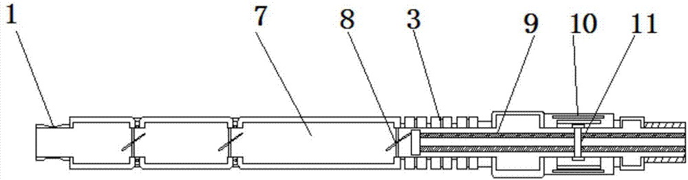
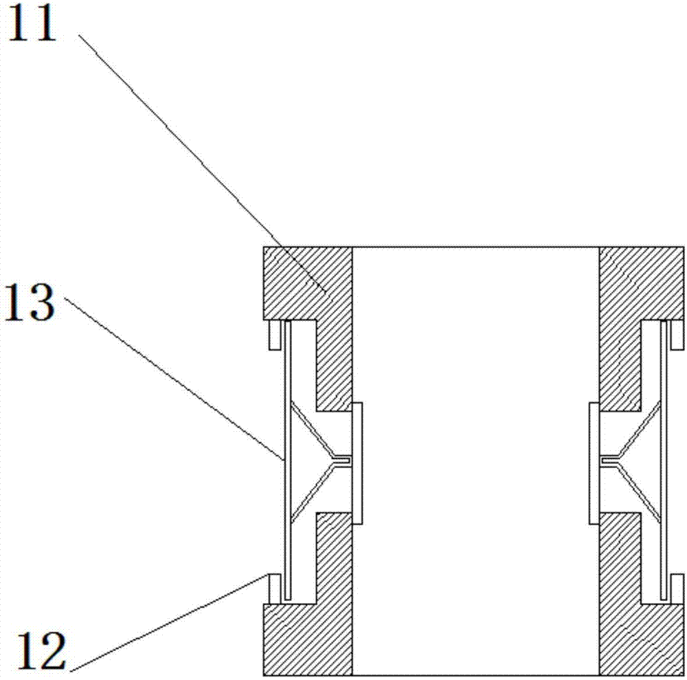
[0020] refer to Figure 1-4 , a pressure-resistant packer, including a shell 2, a sleeve 1 is welded on one side of the shell 2, and a first connecting seat is welded on the other side of the shell 2, and the first connecting seat is far away from the outer wall of the shell 2 on one side There is a card slot, and the inner wall of the card slot is inserted with a setting sleeve 9, and the outer wall of one end of the setting sleeve 9 close to the shell 2 is sleeved with an elastic sealing sleeve 3, and the central axis of the outer wall on both sides of the setting sleeve 9 is sleeved. A connecting pipe 4 is connected, and the inner wall of the connecting pipe 4 is ...


PUM


Abstract

The invention discloses a pressure-resistant packer. The pressure-resistant packer comprises a shell, a sleeve head is welded to the outer wall of one side of the shell, and a first connecting seat iswelded to the outer wall of the other side of the shell. A clamping groove is formed in the outer side of the side, away from the shell, of the first connecting seat. The inner wall of the clamping groove is connected with a setting sleeve in an inserted mode. An elastic sealing sleeve is connected with the outer wall of the end, close to the shell, of the setting sleeve in a sleeving mode. Connecting pipes are connected with the central axis positions of the outer walls of the two sides of the setting sleeve in a sleeving mode. A second clamping groove is formed in the inner wall of each connecting pipe. The inner wall of each second clamping groove is connected with a sleeve in a clamped mode. According to the pressure-resistant packer, through the elastic sealing sleeve and an anchor,the defects that the existing operation that setting and de-sealing of the packer are controlled by using upward-lifting and downward-placing of a pipe column is cumbersome and long in time consumingare effectively avoided; a multi-stage de-sealing pipe is matched with an upward flipping plate, in-advance de-sealing of an existing packer during failure of a hydraulic circuit can be solved; and through an I-shaped slip sleeve, the supporting property is good, and the upper setting sleeve is matched, the setting state of the packer is not affected, and setting is reliable.

Description

technical field [0001] The invention relates to the technical field of packers, in particular to a packer with strong pressure resistance. Background technique [0002] Packers are divided into rotating seat packers and non-rotating seat packers, of which non-rotating seat packers include mechanical packers that are raised and lowered and various types of hydraulic packers. The lifting and lowering mechanical packer uses the lifting and lowering of the pipe string to control the sealing and unsealing of the packer. After searching, the Chinese patent authorization number is CN201710238504.0, which discloses a deep water packer device , including an upper joint, a central tube, a lower joint, slips, rubber pads, sliding sleeves and lock sleeves. The top end of the central tube is threaded with an upper joint; the bottom end of the central tube is threaded with a lower joint. Slips are installed through the upper vertebral body, and the center pipe below the upper vertebral b...

Claims


Application Information

Patent Timeline
Patent Type & Authority Applications(China)
IPC IPC(8): E21B33/126E21B33/1295
CPCE21B33/126E21B33/1295
Inventor 张淞源张虎
Owner DAQING TIANDEZHONG PETROLEUM SCI & TECH CO LTD
Why Eureka
Try Eureka