
Box body of gearbox for rail transit vehicle

A technology for rail transit vehicles and gearboxes, which is applied in the field of rail vehicle transmission systems and can solve problems such as the inability of the lubrication system to meet the requirements of working conditions.

Pending Publication Date: 2018-04-06
BEIJING NANKOU RAILWAY TRANSIT MACHINERY
View PDF9 Cites 3 Cited by
  • Summary
  • Abstract
  • Description
  • Claims
  • Application Information

AI Technical Summary

Problems solved by technology

[0004] The invention provides a gear box of a rail transit vehicle, which solves the problem that the structural strength of the box and the lubricating system in the prior art cannot meet the requirements of high-speed operation, strengthens the structural strength of the box, and improves the lubricating system. The performance guarantees the working condition requirements of the EMU trains at high speeds

Method used


Image

  • Box body of gearbox for rail transit vehicle
  • Box body of gearbox for rail transit vehicle
  • Box body of gearbox for rail transit vehicle

Examples


Embodiment Construction

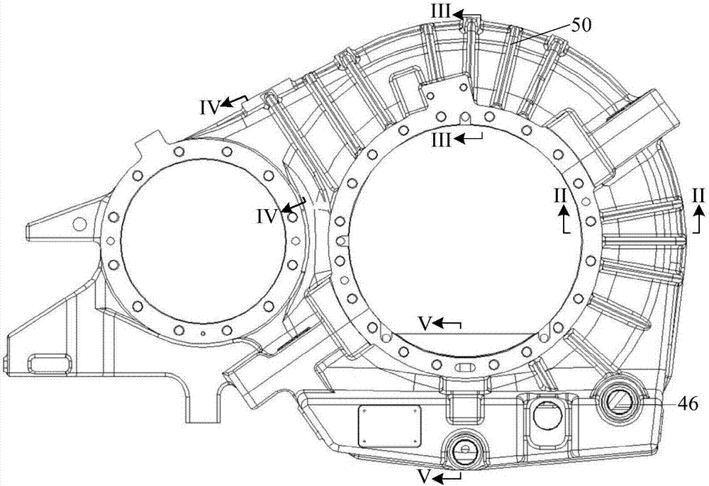
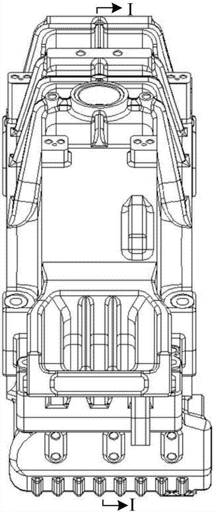
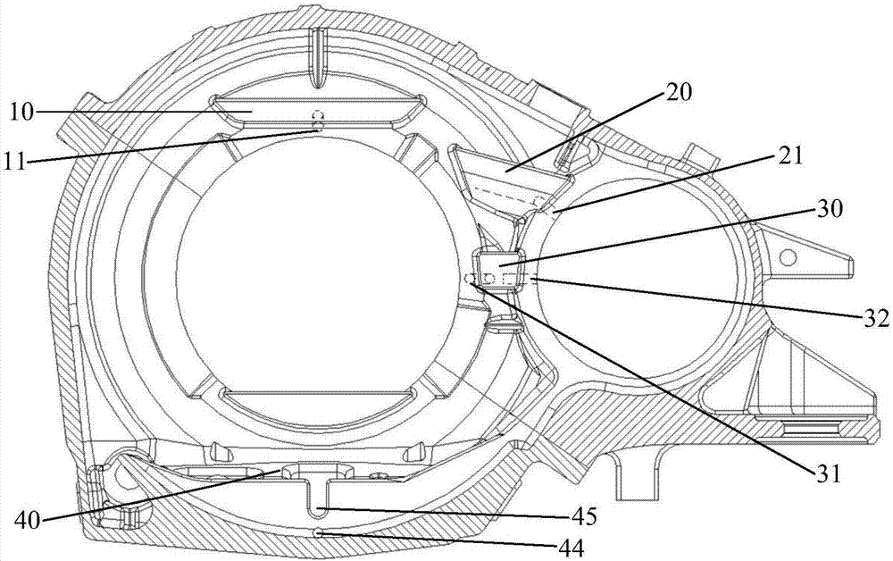
[0027] figure 1 The front view of the box body of the gear box of the rail transit vehicle provided by the present invention, figure 2 The left view of the casing of the gear box of the rail transit vehicle provided by the present invention; image 3 for figure 2 Schematic diagram of the cross-sectional structure along the I-I line, Figure 4 for figure 1 Schematic diagram of the cross-sectional structure along the line II-II. Such as Figure 1 to Figure 3 As shown, the case body of the gear box provided in this embodiment includes: an output end oil sump 10, an input end oil sump 20, a middle oil sump 30 and an oil tank 40, wherein one end of the two opposite side walls of the case body is connected to the The top of the box is trapezoidal, and the other ends of the two opposite side walls of the box are bent outward in a circular arc shape; the output oil sump 10 and the input oil sump 20 are arranged on the upper inner wall of the box, and the middle position The oi...


PUM


Abstract

The invention provides a box body of a gearbox for a rail transit vehicle. The box body comprises an output-end oil collection groove, an input-end oil collection groove, a middle-position oil collection groove and an oil tank, wherein the output-end oil collection groove and the input-end oil collection groove are formed in the upper part of the inner wall of the box body, and the middle-positionoil collection groove is located below the input-end oil collection groove, and located between an output-end bearing installation position and an input-end bearing installation position; output-endoil inlet holes are formed in the bottom of the output-end oil collection groove and the first sidewall of the middle-position oil collection groove, and used for lubricating an output-end bearing; the input-end oil collection groove is inclined downwards, input-end oil inlet holes are formed in the lower part of the sidewall of the input-end oil collection groove and the second sidewall of the middle-position oil collection groove, and used for lubricating an input-end bearing, and the second sidewall and the first sidewall are oppositely arranged; and the oil tank is arranged at the bottom of the box body. The box body provided by the invention can meet the working condition requirement during the high-speed running of multiple unit trains.

Description

technical field [0001] The invention relates to the technical field of rail vehicle transmission systems, in particular to a box body of a gear box of a rail vehicle. Background technique [0002] The gearbox of the rail transit vehicle is located at the lower part of the car body, suspended on the axle of the motor car, and directly bears the impact of the rail on the wheel set, and the working conditions are very harsh. [0003] The current rail transit gearboxes are mostly suitable for EMU trains with a speed of 250 kilometers per hour and below. For high-speed EMU trains with a speed of 350 kilometers per hour, the structural strength and lubrication system of the box in the prior art cannot meet the requirements of high-speed operation. Condition requirements. Therefore, it is necessary to propose a gearbox casing that can meet the working condition requirements of the high-speed operation of the EMU train. Contents of the invention [0004] The invention provides a...

Claims


Application Information

Patent Timeline
IPC IPC(8): F16H57/02F16H57/04F16H57/03
CPCF16H57/02F16H57/03F16H57/0424F16H57/0471
Inventor 王首一
Owner BEIJING NANKOU RAILWAY TRANSIT MACHINERY
Learn More