Funnel slag removing device for roller-way slag treatment process

A slag cleaning and funnel technology, which is applied in lighting and heating equipment, etc., can solve the problems of easy adhesion of residual steel slag, large labor, and threats to the personal safety of operators, and achieves the effect of compact structure, economical investment and low cost.

Inactive Publication Date: 2018-04-06
SHANGHAI BAOSTEEL ENERGY TECH
View PDF7 Cites 0 Cited by
  • Summary
  • Abstract
  • Description
  • Claims
  • Application Information

AI Technical Summary

Problems solved by technology

[0003] When using this device to process steel slag, the high-temperature slag first passes through the receiving hopper before entering the core processing device - the drum device, and the inner wall of the steel structure part of the funnel tends to adhere to the residual steel slag due to the influence of the high-temperature slag on the receiving hopper In the past, on-site operators manually processed the hot slag at the end of the previous tank and before the start of the second tank of hot slag. Under the normal operating system to ensure annual production, the interval between the front and rear The time is only 10-15 minutes, so this is a considerable amount of labor for the on-site personnel, not to mention that the temperature of the steel structure of the receiving funnel is as high as 700°C-800°C during the hot slag operation of the receiving funnel. ℃, the operators are directly exposed to heat waves during the slag removal process, and more importantly, it is a great threat to the personal safety of the operators

Method used


Image

  • Funnel slag removing device for roller-way slag treatment process
  • Funnel slag removing device for roller-way slag treatment process
  • Funnel slag removing device for roller-way slag treatment process

Examples


Embodiment 1

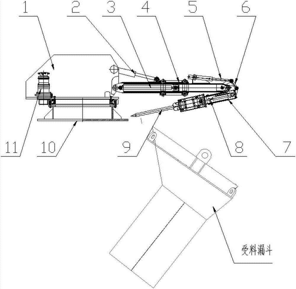
[0031] See figure 1 , the funnel slag removal device of this embodiment is used for the drum slag treatment process, and the funnel is marked as "receiving funnel" in the figure, and the funnel slag removal device includes:

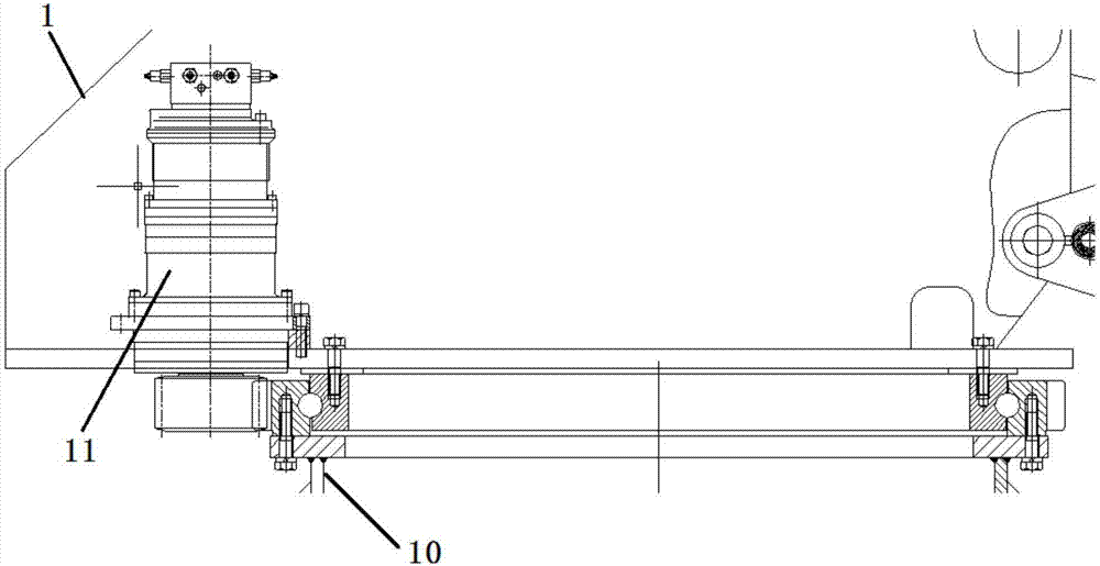
[0032] support frame one (1);

[0033] Support frame two (10);

[0034] hydraulic motor (11);

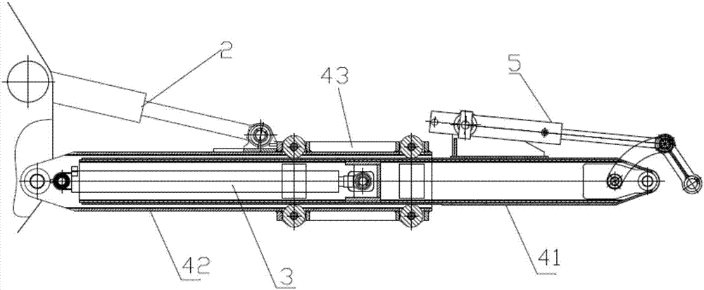
[0035] One hydraulic cylinder or one pneumatic cylinder (2);

[0036] Two hydraulic cylinders or two pneumatic cylinders (3);

[0037] Sliding sleeve one (4);

[0038] Hydraulic cylinder three or pneumatic cylinder three (5);

[0039] Connecting rod structure (6);

[0040] Sliding sleeve two (7);

[0041] Four hydraulic cylinders or four pneumatic cylinders (8);

[0042] Bit (9);

[0043] in,

[0044] The support frame two (10) is arranged on a suitable operating platform according to the process layout requirements, and the support frame one (1) realizes its relative to the support frame through the hydraulic motor (11) and the rotary support structu...


PUM


Abstract

The invention discloses a funnel slag removing device for a roller-way slag treatment process. The funnel slag removing device comprises a first supporting frame, a second supporting frame, a hydraulic motor, a first hydraulic cylinder or a first pneumatic cylinder, a second hydraulic cylinder or a second pneumatic cylinder, a first sliding sleeve, a third hydraulic cylinder or a third pneumatic cylinder, a connecting rod structure, a second sliding sleeve, a fourth hydraulic cylinder or a fourth pneumatic cylinder, and a drill bit; the first supporting frame enables other components of the funnel slag removing device to move by 360 degrees in the circumferential direction through the hydraulic motor and a revolving support assembled on the second supporting frame; the first hydraulic (pneumatic) cylinder and the first sliding sleeve are pivotally connected with the first supporting frame so that the first hydraulic (pneumatic) cylinder controls the first sliding sleeve to perform up-and-down arm swinging actions; the second hydraulic (pneumatic) cylinder is mounted on the first sliding sleeve to enable the first sliding sleeve to perform telescopic movement in the axial direction;and the third hydraulic (pneumatic) cylinder is assembled on the first sliding sleeve, the action of the drill bit is directly controlled through the first sliding sleeve, the connecting rod structure and the second sliding sleeve, and therefore the slag removing requirements of each position in the axial direction of a receiving funnel are met.

Description

technical field [0001] The invention relates to a funnel slag removal device suitable for use in a slag treatment process, in particular to a funnel slag removal device suitable for use in a drum method slag treatment process. Background technique [0002] The drum slag treatment device is one of the most advanced slag treatment devices in the world. It has the characteristics of short process, low investment, safety and reliability, and low energy consumption. The treated steel slag can be directly used with less pollution. [0003] When using this device to process steel slag, the high-temperature slag first passes through the receiving hopper before entering the core processing device - the drum device, and the inner wall of the steel structure part of the funnel tends to adhere to the residual steel slag due to the influence of the high-temperature slag on the receiving hopper In the past, on-site operators manually processed the hot slag at the end of the previous tank ...

Claims


Application Information

Patent Timeline
Patent Type & Authority Applications(China)
IPC IPC(8): F23J1/06
Inventor 李嵩戴喜明刘帅冯双红陈诚
Owner SHANGHAI BAOSTEEL ENERGY TECH
Why Eureka
Try Eureka