Method for improving location precision of micro seismic sources for mining

A technology of source location and microseismic, applied in the direction of seismic signal processing, etc., can solve the problems of limited seismic range with microseismic location accuracy, large amount of calculation, large location error, etc. Effect

Active Publication Date: 2018-04-06
BEIJING GENERAL RES INST OF MINING & METALLURGY
View PDF8 Cites 27 Cited by
  • Summary
  • Abstract
  • Description
  • Claims
  • Application Information

AI Technical Summary

Problems solved by technology

[0016] However, the disadvantages of this scheme are: 1) In actual engineering, the rock mass in the microseismic monitoring area is not a uniform medium, and the seismic wave velocity in different areas is different. Using the traditional single-velocity positioning model, it is impossible to accurately calculate the time, and the positioning error is large. Suitable for microseismic high-precision positioning in complex rock mass environments in mines
Each repetition of the process is called an "iteration", and the result of each iteration will be used as the initial value of the next iteration. When the result deviation is too large, it is easy to cause the iteration to not converge, resulting in too large error, and the calculation amount of this method is too large, and the accuracy of microseismic location and the range of locating earthquakes are limited.

Method used


Image

  • Method for improving location precision of micro seismic sources for mining
  • Method for improving location precision of micro seismic sources for mining
  • Method for improving location precision of micro seismic sources for mining

Examples


Embodiment 1

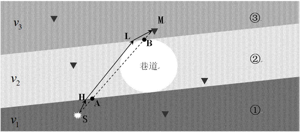
[0045] Such as image 3 As shown, it is assumed that the velocity structure characteristics of the microseismic monitoring area (mine roadway, goaf, ore body, surrounding rock mass and other mine complex rock mass structures) are composed of three parallel rock layers and roadways with different wave velocities, which are compiled sequentially from bottom to top as Wave velocity zone 1, wave velocity zone 2 and wave velocity zone 3 ( image 3 The middle numbers correspond to ①, ② and ③). The corresponding wave velocity values ​​in the wave velocity region are denoted as V 1 , V 2 and V 3 , the roadway passes through the second layer, and the propagation of seismic waves does not pass through the hollow area of ​​the roadway. When the actual seismic wave propagates between different media, it follows the Huygens principle and the Fermat principle and propagates according to the broken line. The embodiment of the present invention divides the mine rock mass through self-adap...


PUM


Abstract

The invention discloses a method for improving the location precision of micro seismic sources for mining. Through wave velocity zoning, a wave velocity model is more in line with the velocity structure characteristics of the complex rock masses of mines in a micro seismic monitoring area (such as a mine roadway, a goaf, an ore body or a surrounding rock), the extraction precision of the actual arrival time of seismic wave is higher, and thus, the precision of seismic source inversion and location is improved. In the process of seismic source inversion and location, an initial iteration seismic source parameter depth threshold is set through the layout and monitoring range of the space envelope of wave detectors, and a weighting factor is introduced during inversion according to the waveform quality. Therefore, the location precision of seismic sources is improved.

Description

technical field [0001] The invention relates to the technical field of microseismic monitoring, in particular to a method for improving the positioning accuracy of mine microseismic sources. Background technique [0002] The mine has gradually entered the deep mining stage, and problems such as rock bursts and landslides caused by high stress and high rock pressure have become major hidden dangers restricting mine safety production. In the process of deformation and failure of mine rock mass, cracks are generated, expanded, and rubbed, and the accumulated energy is released, resulting in microseismic events. The microseismic monitoring system receives the waveform of microseismic events (weak seismic events) through the geophones distributed inside the mine rock mass, and by extracting the arrival time of the microseismic waveform, according to the waveform quality and the characteristics of the wave velocity structure of the mine site, an appropriate positioning algorithm c...

Claims


Application Information

Patent Timeline
Patent Type & Authority Applications(China)
IPC IPC(8): G01V1/28
Inventor 戴锐张达冀虎乔莎石雅倩杨小聪
Owner BEIJING GENERAL RES INST OF MINING & METALLURGY
Why Eureka
Try Eureka