Check patentability & draft patents in minutes with Patsnap Eureka AI!

Stator structure and resolver

A stator and structure technology, applied in the direction of magnetic circuit shape/style/structure, winding insulation shape/style/structure, electromechanical devices, etc., can solve problems such as component deformation and reliability reduction of resolvers, and achieve reliability improvement. Effect

Active Publication Date: 2018-04-06
MINEBEAMITSUMI INC
View PDF21 Cites 0 Cited by
  • Summary
  • Abstract
  • Description
  • Claims
  • Application Information

AI Technical Summary

Problems solved by technology

[0005] However, in the above configuration example, the first bobbin casing and the second bobbin casing and the first insulating bobbin casing and the second bobbin casing are made of resin, so it is difficult to manufacture them with high precision. The size of each component is to make the first bending part and the third bending part contact with each other over the entire circumference, and make the second bending part and the fourth bending part contact with each other over the entire circumference to prevent the intrusion of foreign matter. pressure abutment
As a result, one or both parts may be deformed, and the reliability of the resolver may be reduced.

Method used


Image

  • Stator structure and resolver
  • Stator structure and resolver
  • Stator structure and resolver

Examples


no. 1 approach

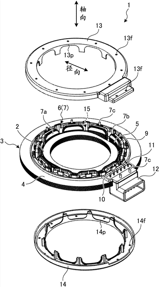
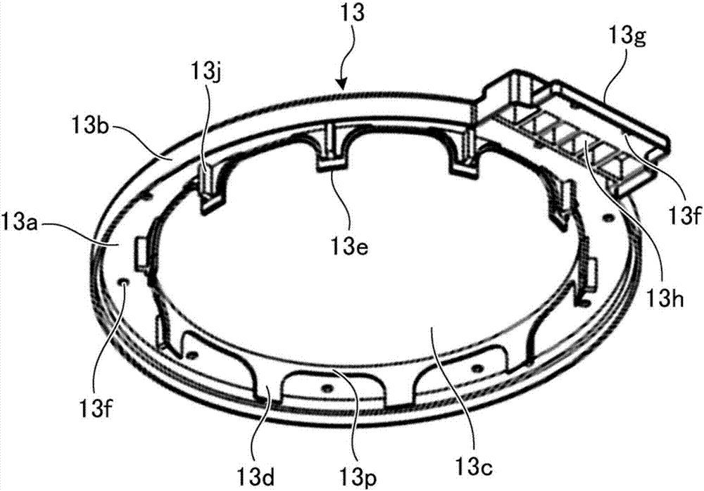
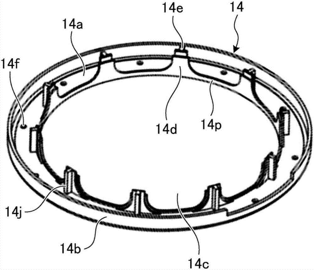
[0028] figure 1 It is a schematic exploded perspective view of the resolver related to the first embodiment. Such as figure 1 As shown, the resolver 1 of the first embodiment is a VR (variable reluctance) resolver having a rotor 2 , a stator 3 , a first coil cover 13 , and a second coil cover 14 . The stator 3, the first coil cover 13, and the second coil cover 14 constitute a stator structure.

[0029] The rotor 2 has a laminated structure in which a plurality of steel cores made of soft magnetic materials such as silicon steel plates are laminated, is attached to a rotating shaft of a motor (not shown), and is arranged inside the stator 3 . figure 1 The indicated axial direction corresponds to the axial direction of the rotation shaft of the motor connected to the rotor 2 . Additionally, if figure 1 As shown, the radial direction and the direction perpendicular to the axial direction coincide. In addition, the radial direction refers to all directions parallel to the pl...

no. 2 approach

[0063] In the second embodiment, a case where a structure in which a flange portion of an insulator and a coil cover are opposed to each other with a slight gap therebetween is applied to a resolver having a different structure from the resolver 1 of the first embodiment will be described.

[0064] Figure 11 It is a schematic exploded perspective view of the resolver of the second embodiment. in addition, Figure 12 yes Figure 11 The E-E line sectional view of the resolver shown, Figure 13 yes Figure 11 The F-F line sectional view of the resolver shown.

[0065] Such as Figures 11 to 13 As shown, the resolver 100 of the second embodiment is a VR (Variable Reluctance) resolver having a rotor 20 , a stator 30 , a first coil cover 130 , and a second coil cover 140 . The stator 30, the first coil cover 130, and the second coil cover 140 constitute a stator structure.

[0066] The rotor 20 has a laminated structure in which a plurality of steel cores made of a soft magn...


PUM


Abstract

A stator structure and a resolver further improve reliability. The stator structure according to an embodiment includes a stator core having a plurality of teeth; insulators configured to cover the teeth; a coil wound around each of the teeth with the insulators interposed therebetween; and first and second coil covers configured to cover the coil, each of the first and second coil covers being formed in an annular shape. The insulators have respective flange parts configured to cover respective distal end portions of the teeth. Each of the first and second coil covers has a first peripheral wall. The first peripheral wall of the first coil cover and the flange part located on one side of the insulator are arranged to face each other with a space therebetween. The first peripheral wall ofthe second coil cover and the flange part located on the other side of the insulator are arranged to face each other with a space therebetween.

Description

technical field [0001] The invention relates to stator constructions as well as resolver transformers. Background technique [0002] A resolver is known as a rotation angle sensor. The resolver is composed of a stator having a plurality of teeth extending radially from a wheel-shaped stator core, and a rotor arranged to face the teeth of the stator. Stator wires are wound around the teeth via insulators to form coils. The stator winding consists of an excitation winding for inputting an excitation signal and two detection windings for outputting a two-phase signal according to the rotation angle of the rotor. A sin-phase signal depending on sinθ and a cos-phase signal depending on cosθ are respectively output from the detection winding. A resolver is known in which two coils covering the stator winding are attached to both sides of the stator core in order to prevent foreign matter such as cutting chips from entering the stator winding (coil) side even when used in oil. ...

Claims


Application Information

Patent Timeline
Patent Type & Authority Applications(China)
IPC IPC(8): H02K5/10H02K3/34H02K24/00
CPCH02K3/345H02K5/10H02K24/00H02K3/34H02K5/08H02K5/225H02K2203/09H02K1/16H02K3/32H02K3/48
Inventor 阿部纮志山田尚浩松浦睦
Owner MINEBEAMITSUMI INC
Features
  • R&D
  • Intellectual Property
  • Life Sciences
  • Materials
  • Tech Scout
  • Unparalleled Data Quality
  • Higher Quality Content
  • 60% Fewer Hallucinations
Learn More