
Power amplifiers for RF transceivers, RF transceivers, remote controls

A power amplifier and radio frequency transceiver technology, applied in the field of radio frequency, can solve the problems that affect the normal operation of the circuit and increase the difficulty of power circuit design

Active Publication Date: 2022-04-22
HISENSE VISUAL TECH CO LTD
View PDF3 Cites 0 Cited by
  • Summary
  • Abstract
  • Description
  • Claims
  • Application Information

AI Technical Summary

Problems solved by technology

[0005] This application provides a power amplifier, a radio frequency transceiver, and a remote controller applied to a radio frequency transceiver, which are used to solve the problem of setting two power supply voltages or setting a power conversion circuit in the power amplifier in the related art, which may affect the normal operation of the circuit, and increase the power supply. Difficulty in circuit design

Method used


Image

  • Power amplifiers for RF transceivers, RF transceivers, remote controls
  • Power amplifiers for RF transceivers, RF transceivers, remote controls
  • Power amplifiers for RF transceivers, RF transceivers, remote controls

Examples


Embodiment Construction

[0048] In order to make the purpose, technical solution and advantages of the present application clearer, the present application will be described in detail below in conjunction with the accompanying drawings and specific embodiments.

[0049] Explanation of terms: PMOS tube refers to P-channel MOS tube (Metal Oxide Semiconductor, metal oxide semiconductor); NMOS tube refers to N-channel MOS tube.

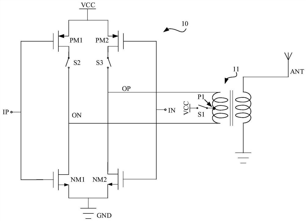
[0050] The application provides a power amplifier applied to a radio frequency transceiver, figure 2 It is the circuit structure diagram of the power amplifier provided by this application. see figure 2 , the power amplifier includes a bridge power amplifying unit 10, a balun device 11 and a first switch S1, and the bridge power amplifying unit 10 includes a second switch S2 and a third switch S3.

[0051] Wherein, one end of the first switching tube S1 is connected to the power supply VCC of the bridge power amplifying unit 10, and the other end is connected to the common mo...


PUM


Abstract

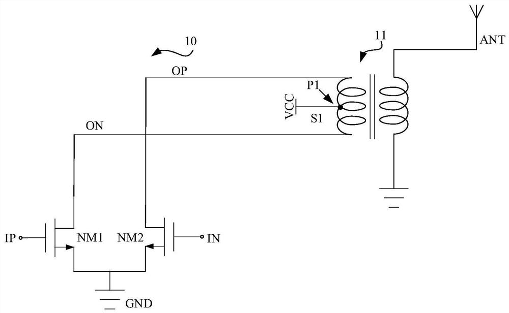
The application provides a power amplifier, a radio frequency transceiver, and a remote controller applied to a radio frequency transceiver. The power amplifier includes a bridge-type power amplifying unit, a balun device, and a first switch tube; one end of the first switch tube is connected to a power supply, and the other end is connected to a common mode point of the balun device; the bridge-type power amplifying unit includes: a second switch tube , one end is connected to the drain of the first PMOS transistor, the other end is connected to one end of the input side of the balun device; One end; when the power amplifier works in the first mode, the first switch tube is turned on, and the second and third switch tubes are turned off; when the power amplifier works in the second mode, the first switch tube is turned off, and the second and third switch tubes are turned on Pass. The present application can output voltages of two different magnitudes without relying on external circuits, thereby realizing power outputs of two different magnitudes.

Description

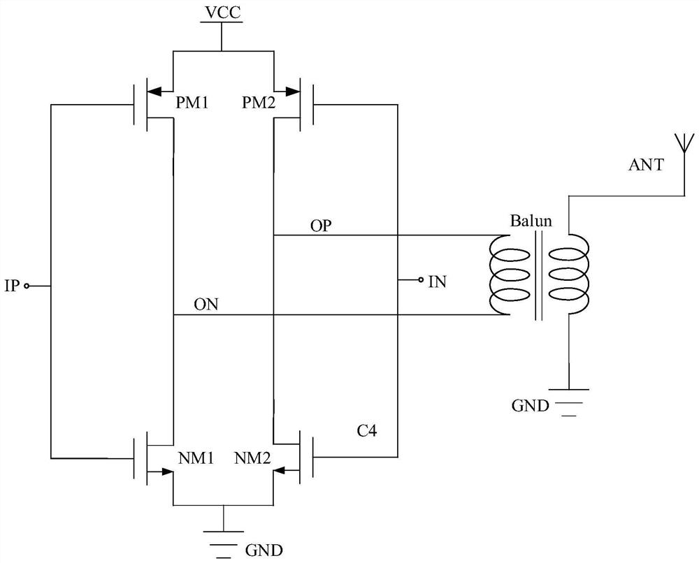
technical field [0001] This application relates to radio frequency technology, in particular to power amplifiers, radio frequency transceivers and remote controllers applied to radio frequency transceivers. Background technique [0002] In a radio frequency transceiver, the modulated radio frequency signal needs to be transmitted to the antenna (ANT) through a power amplifier. figure 1 The structure of the power amplifier is shown. see figure 1 , The power amplifier mainly includes: a bridge power amplifying unit and a Balun device (Balun). Wherein, the bridge power amplifying unit has two input terminals IP and IN, and two output terminals OP and ON, and the two output terminals OP and ON of the bridge power amplifying unit are respectively connected to two ends of the balun device. When the bridge power amplifying unit receives the modulated differential radio frequency signal through the input terminals IP and IN, it amplifies the radio frequency signal and outputs it ...

Claims


Application Information

Patent Timeline
Patent Type & Authority Patents(China)
IPC IPC(8): H03F3/19H03F3/21H03F3/24
CPCH03F3/19H03F3/21H03F3/245H03F2200/451
Inventor 孙文
Owner HISENSE VISUAL TECH CO LTD
Learn More