A Heterogeneous Diode Clamped Three-Level Rectifier

A technology of diode clamping and three-level rectification, which is applied in the direction of electrical components, high-efficiency power electronic conversion, output power conversion devices, etc., to achieve the effect of small common-mode interference, reduce input current ripple, and improve work reliability

Active Publication Date: 2022-05-20
CHINA THREE GORGES UNIV
View PDF10 Cites 0 Cited by
  • Summary
  • Abstract
  • Description
  • Claims
  • Application Information

AI Technical Summary

Problems solved by technology

The switching loss of the switching tube in the traditional two-level converter is obviously greater than that of the multi-level converter

Method used


Image

  • A Heterogeneous Diode Clamped Three-Level Rectifier
  • A Heterogeneous Diode Clamped Three-Level Rectifier
  • A Heterogeneous Diode Clamped Three-Level Rectifier

Examples


Embodiment Construction

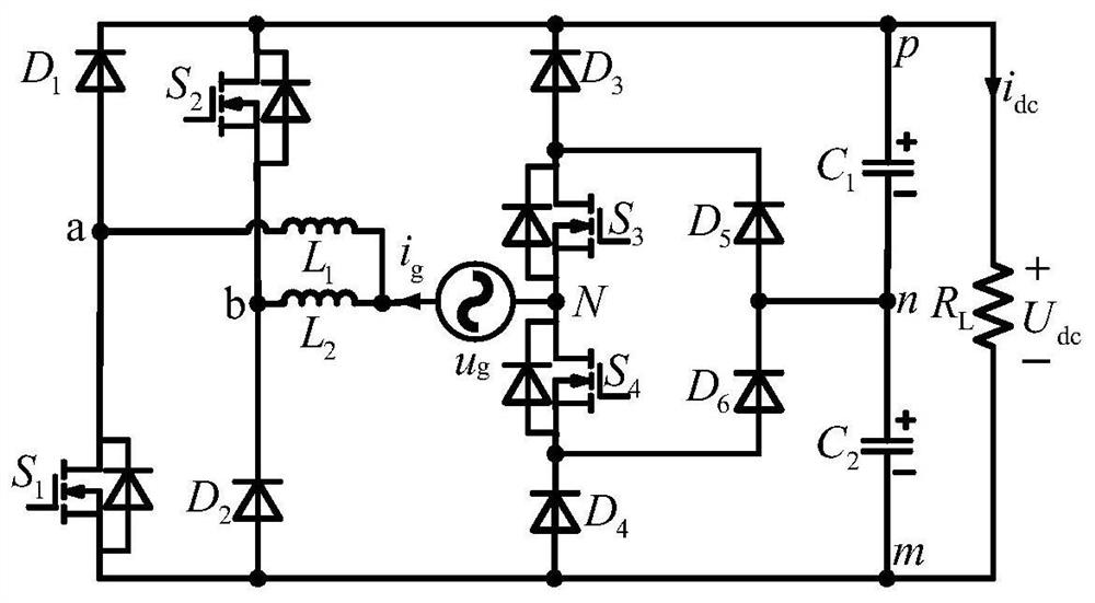
[0045] Such asfigure 1 As shown, a heterogeneous diode-clamped three-level pseudo-totem pole rectifier,

[0046] The inventive rectifier includes a switching tube S 1 , S 2 , S 3 , S 4 , Diode D 1 ~D 6 , AC power u g , inductance L 1 , L 2 , capacitance C 1 、C 2 ;

[0047] The pseudo-totem pole consists of diode D 1 , switch tube S 1 , inductance L 1 with diode D 2 , switch tube S 2 , inductance L 2 , whose structure is connected as figure 1 shown.

[0048] The diode on the left side of the rectifier D 1 , switch tube S 1 , inductance L 1 with diode D 2 , switch tube S 2 , inductance L 2 Two pseudo-totem pole bridge arms are respectively formed; the right side is the switch tube S 3 , S 4 , Diode D 3 、D 4 、D 5 、D 6 Composed of heterogeneous bidirectional tube clamping three-level structure.

[0049] Series Split Capacitor C 1 、C 2 To form a DC bus, since the series capacitors are equal in size, each capacitor bears the DC bus voltage U dc half ...


PUM


Abstract

A heterogeneous diode-clamped three-level rectifier, AC power u g one side with a shunt inductor L 1 , L 2 connected, the inductance L 1 Switch tube S 1 drain and D 1 Anode connection, forming node a; inductance L 2 with diode D 2 Cathode and S 2 source, forming node b; AC source u g The other side is connected with the switching tube S 3 source and S 4 The drains are connected to form node N; diode D 1 Cathode, D 3 Cathode, switch tube S 2 drain and capacitance C 1 Anode connected to node p; diode D 2 Anode, D 4 Anode, switch tube S 1 source and capacitance C 2 The cathode is connected to the node m; the diode D 5 Anode, D 6 Cathode and Split Capacitor C 1 、C 2 connected to node n. The invention discloses a three-level rectifier of heterogeneous diode clamping type. The rectifier can reduce the switching loss of the switch tube, reduce the harmonic wave and the voltage stress of the switch tube, and has high reliability.

Description

technical field [0001] The invention relates to the field of multilevel converters, in particular to a three-level rectifier of heterogeneous diode clamping type. Background technique [0002] With the development of DC transmission, the traditional two-level converter is gradually being replaced by the emerging multi-level converter. The research purpose of multilevel converter is to improve the configuration of power circuit to obtain higher efficiency, reliability, lower harmonic and voltage stress. The switching loss of the switching tube in the traditional two-level converter is obviously greater than that of the multi-level converter. The switching loss of the switch tube is expressed in the form of heat. In order to control the temperature of the switch tube not to exceed the allowable value, the heat loss can only be reduced by reducing the number of times the switch is turned on and off. [0003] The voltage stress of the switching tube in the traditional two-leve...

Claims


Application Information

Patent Timeline
Patent Type & Authority Patents(China)
IPC IPC(8): H02M7/219H02M7/797H02M1/42H02M1/32
CPCH02M7/219H02M7/797H02M1/4225H02M1/4233H02M1/32Y02B70/10
Inventor 马辉敬成徐甜川郑凯通
Owner CHINA THREE GORGES UNIV
Why Eureka
Try Eureka