

Cell switching method, apparatus and system
A cell handover and cell technology, applied in the field of communication, can solve the problems of data transmission interruption and inability to trigger data recovery in time.
- Summary
- Abstract
- Description
- Claims
- Application Information
AI Technical Summary
Problems solved by technology
Method used
Image

Examples
Embodiment 1
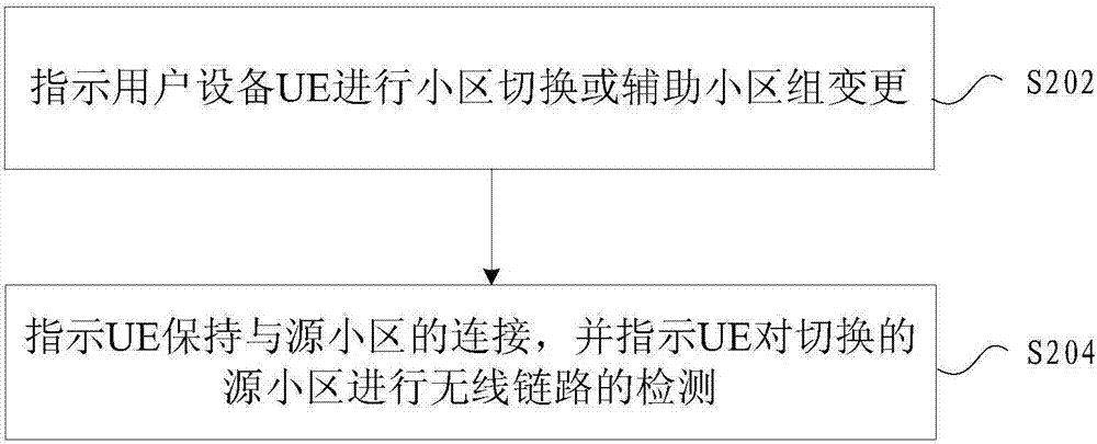
[0072] In this embodiment, a cell handover method is provided, figure 2 is a flow chart of a method for cell handover according to an embodiment of the present invention, such as figure 2 As shown, the process includes the following steps:
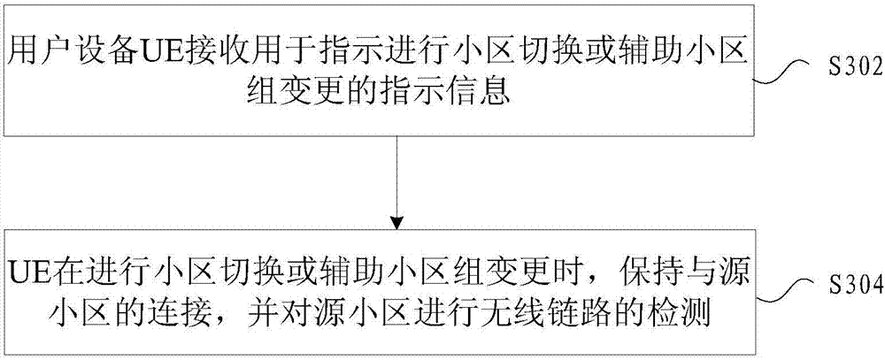
[0073] Step S202, instructing the user equipment UE to perform cell handover or auxiliary cell group change;
[0074] Step S204, instructing the UE to maintain the connection with the source cell, and instructing the UE to perform radio link detection on the handover source cell.
[0075] Through the above steps, during the mobility process of the UE, while maintaining the connection with the source cell, by starting the radio link detection, the radio link recovery can be performed quickly when a radio link problem occurs. It solves the technical problem in the related art that the data recovery process cannot be triggered in time when an error occurs in the physical layer and the data cannot be sent and received during the cell hando...
Embodiment 2
[0111]This embodiment also provides a device and system for cell handover, the device is used to implement the above embodiments and preferred implementation modes, what has already been described will not be repeated. As used below, the term "module" may be a combination of software and / or hardware that realizes a predetermined function. Although the devices described in the following embodiments are preferably implemented in software, implementations in hardware, or a combination of software and hardware are also possible and contemplated.
[0112] Figure 4 is a structural block diagram of a device for cell handover according to an embodiment of the present invention, such as Figure 4 As shown, the source base station or main base station applied on the network side includes:
[0113] The first instructing module 40 is configured to instruct the user equipment UE to perform cell handover or assist cell group change;
[0114] The second instructing module 42 is configure...
Embodiment 3
[0143] This embodiment is an optional embodiment according to the present invention, and is used to describe this application in detail in combination with specific scenarios:
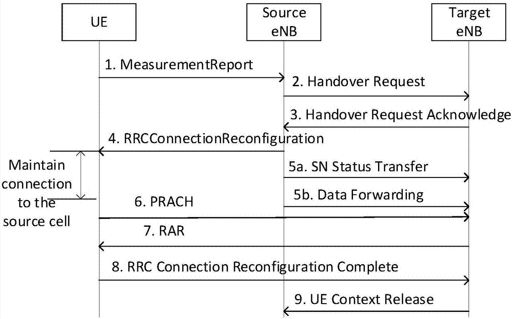
[0144] This embodiment provides a process of changing a serving base station (cell) for a UE in an LTE system, including single connection handover; dual connection handover; addition and change of a secondary base station under dual connection, and the UE still needs to maintain a period of time with the source base station The connection indicates the processing behavior of a specific UE through the network, thereby reducing the service interruption delay and packet loss of the UE.
[0145] The technical problem to be solved in this embodiment is that, in the make-before-break solution in the related art, since it is not determined that the UE will stop the detection of the physical layer wireless link after receiving the handover command, the connection between the source base station and the source ...
PUM
 Abstract
Description
Claims
Application Information