
Apparatus for measuring an electric current through a bus bar

A technology for bus bars and equipment, applied in the field of current equipment, can solve the problems of complex and expensive solutions, and achieve the effect of easy manufacturing

Active Publication Date: 2018-04-06
TE CONNECTIVITY GERMANY GMBH
View PDF15 Cites 4 Cited by
  • Summary
  • Abstract
  • Description
  • Claims
  • Application Information

AI Technical Summary

Problems solved by technology

However, such a solution would be very complex and expensive

Method used


Image

  • Apparatus for measuring an electric current through a bus bar
  • Apparatus for measuring an electric current through a bus bar
  • Apparatus for measuring an electric current through a bus bar

Examples


Embodiment Construction

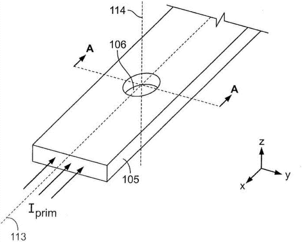
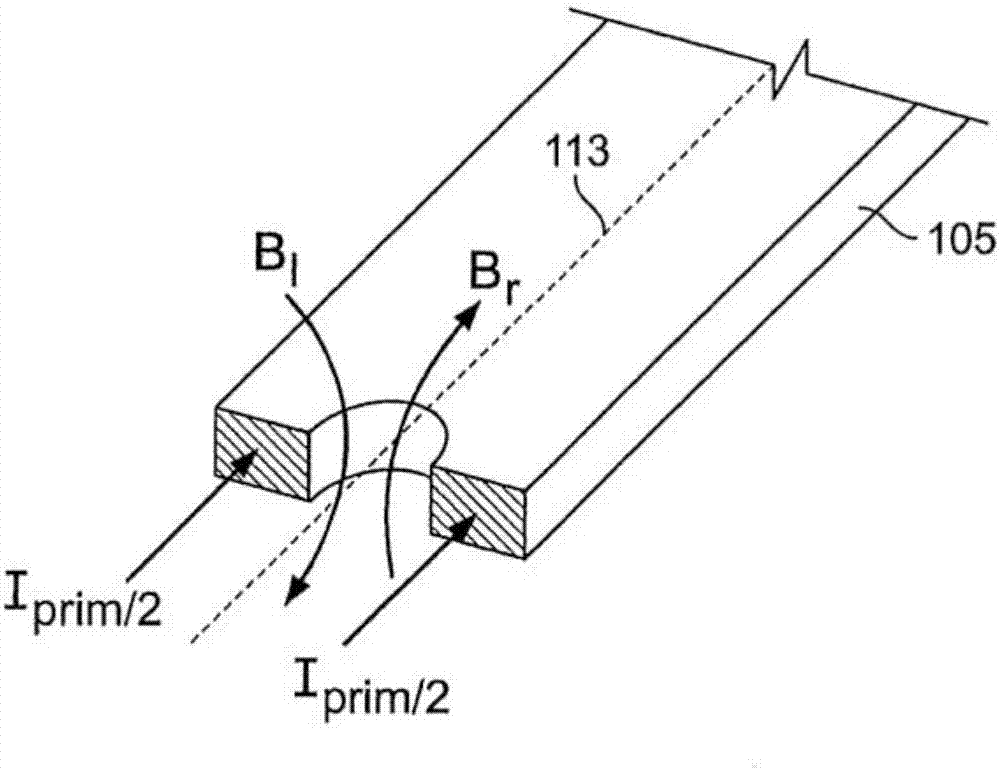
[0022] Figure 2a shows the bus bar 105 and the current I flowing through the bus bar 105 prim and the current intensity of this current is intended to be measured / determined by means of the device according to the invention. The bus bar 105 has a box shape and a longitudinal axis 113, the current I prim Transmission along longitudinal axis 113 . However, the present invention is not limited to box-shaped bus bars. Instead, it also includes other forms, such as cylindrical. The bus bar may also have a bent portion.

[0023] exist Figure 2a In the bus bar 105 shown, a cylindrical through hole 106 is arranged between the upper side and the lower side of the bus bar 105 . The axis of symmetry 114 of the through hole 106 is positioned perpendicular to the longitudinal axis 113 and intersects it. The axis of symmetry 114 is preferably also positioned perpendicularly to the upper and / or lower side of the bus bar 105 such that the through hole 106 is arranged centrally betwee...


PUM


Abstract

The present invention relates to an apparatus for measuring an electric current flowing through a bus bar, which comprises the bus bar itself, a compensation coil and a magnetic field sensor. A through-hole is provided in the bus bar, which divides the electric current flowing through the bus bar into two partial currents that flow round the through-hole. In the through-hole there is provided a compensation coil for generating a compensation field which, at a predetermined position of the through-hole, compensates the magnetic fields generated by the partial currents and an external magnetic field generated outside the apparatus, so that the magnetic flux density of the resulting magnetic field at the predetermined position does not exceed a predetermined threshold. The magnetic flux density of the resulting magnetic field at the predetermined position of the through-hole is detected by the magnetic field sensor which is provided in the through-hole of the bus bar. The compensation coil has a bobbin whose inner part receives the magnetic field sensor, and which is precisely fitted in the through-hole of the bus bar.

Description

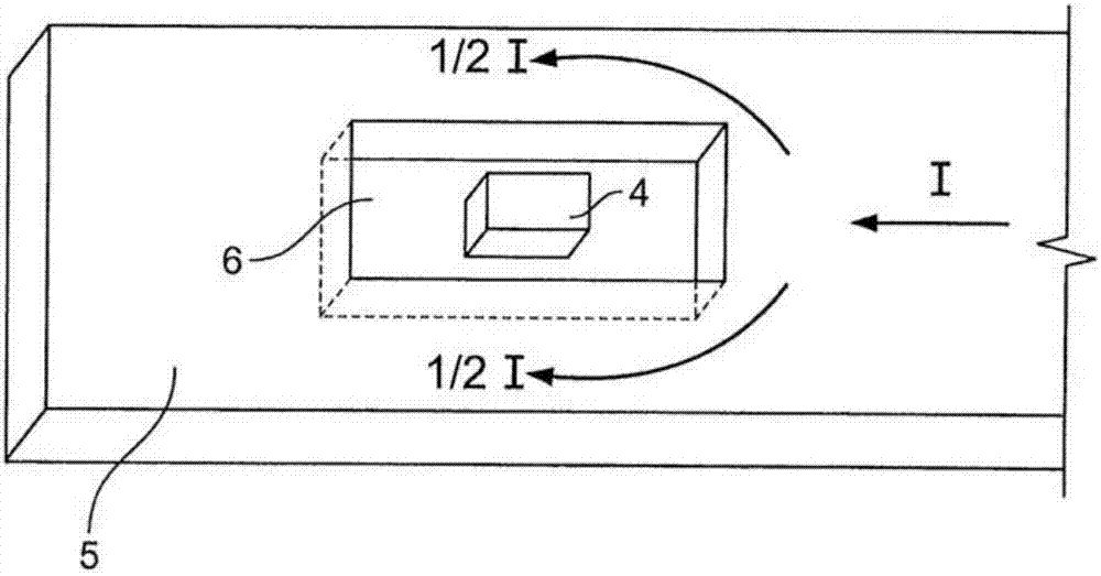
technical field [0001] The present invention relates to a device for measuring current through a bus bar, in particular between a battery and a drive unit in an electric vehicle, and to a battery separation unit in an electric vehicle, which The current is cut off in case the current in the bus bar is too high based on measurements from the device for measuring the current. Background technique [0002] figure 1 A device known from document JP H08 136587 A for measuring the current I flowing through a bus bar 5 is shown. The bus bar 5 of this known device has a rectangular cross-section transverse to the direction of current transmission and has a continuous box-shaped groove 6 positioned symmetrically with respect to the axis of the bus bar 5 . The current I flowing through the bus bar 5 is divided by the groove 6 into two substantially equal partial currents having a current strength of I / 2. These partial currents that flow respectively above and below around the groove...

Claims


Application Information

Patent Timeline
Patent Type & Authority Applications(China)
IPC IPC(8): G01R33/04G01R15/14G01R15/18B60L3/04G01R33/025
CPCG01R33/025G01R33/04G01R15/148G01R15/185
Inventor M.沃尔夫C.伯格(娘家姓:塞赫斯泰特)
Owner TE CONNECTIVITY GERMANY GMBH
Learn More