Honing head capable of improving grinding precision

A honing head and honing technology, which is applied in the direction of honing machine tools, honing tools, metal processing equipment, etc., to achieve the effects of reducing frustration, reducing wear and improving service life

Inactive Publication Date: 2018-04-10
李林
View PDF0 Cites 0 Cited by
  • Summary
  • Abstract
  • Description
  • Claims
  • Application Information

AI Technical Summary

Problems solved by technology

Aiming at the deficiencies in the prior art, the present invention makes certain improvements to the existing honing head to solve the problem of ensuring that the operating state between the oil stone and the base remains stable after the roughness of the inner surface of the workpiece disappears, and preventing the Relative displacement occurs to achieve the purpose of prolonging the service life of the device; when the invention works, the whetstone is placed in the workpiece, and the honing body is driven at the same time to realize the honing process of the whetstone on the inner wall of the workpiece. When the roughness of the inner wall of the workpiece is reduced to the processing In the standard mode, the distance between the oil stone and the inner wall of the workpiece increases, that is, the adjustment rod located in the middle of the honing body starts to be driven, and the adjustment rod moves down until the outer circular surface of the conical protrusion directly cooperates with the inclined surface on the movable end of the adjustment pin , so that the adjusting pin moves outward along the radial direction of the honing body to realize the gap between the oil stone and the inner wall of the workpiece, and finally realize the fine honing of the inner wall of the workpiece;

Method used


Image

  • Honing head capable of improving grinding precision
  • Honing head capable of improving grinding precision

Examples


Embodiment 1

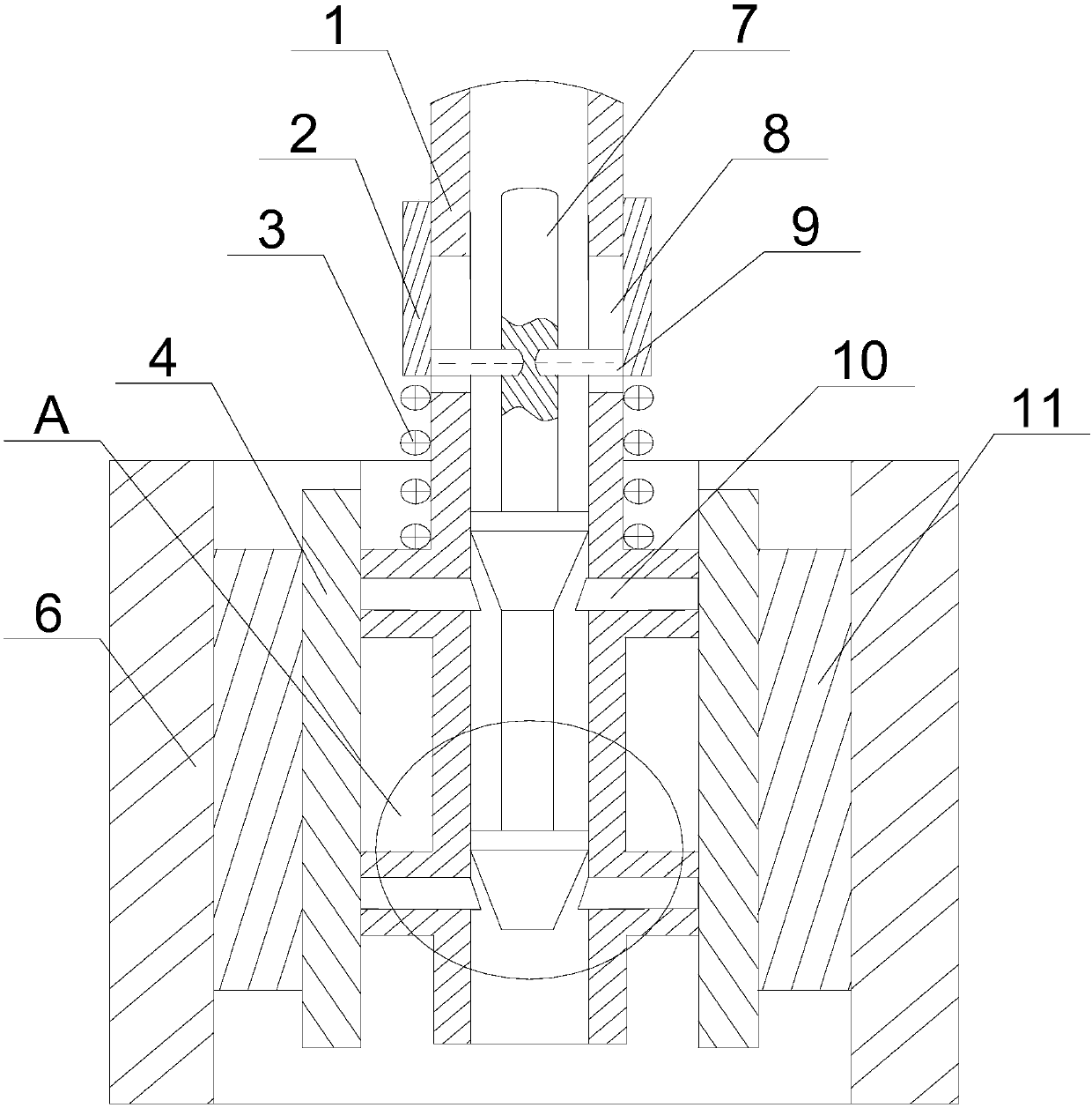
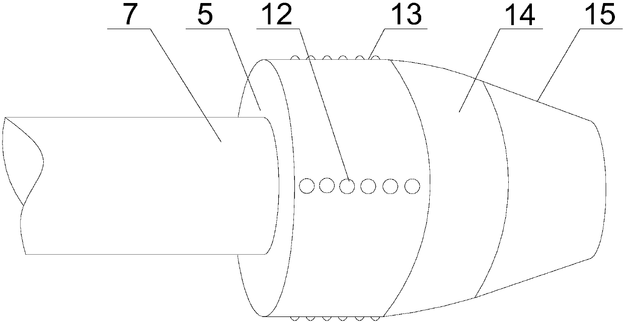
[0023] Such as figure 1 and figure 2 As shown, this embodiment includes a hollow honing body 1 and a plurality of pads 4, a plurality of transition holes are opened on both sides of the honing body 1, and adjustment pins 10 are fixed on the sides of the pads 4, and the adjustment pins 10 cooperates with the gap 14 of the transition hole, the inside of the honing body 1 is slidably provided with an adjustment rod 7, on which a plurality of protrusions 5 are mounted, and the movable end of the adjustment pin 10 is provided with a The protrusion 5 is provided with a smooth circular surface 13 and a conical surface 15, and a transitional circular surface 14 is provided at the junction of the smooth circular surface 13 and the conical surface 15; There is an adjustment hole 8, and an adjustment nut 2 is threaded on the outer wall of the honing body 1, and a pin 9 is fixed on the adjustment nut 2, and the pin 9 passes through the adjustment hole 8 and is connected with the adjustm...


PUM


Abstract

The invention discloses a honing head capable of improving the grinding accuracy, which includes a honing body and a plurality of pads, a plurality of transition holes are opened on both sides of the honing body, adjustment pins are fixed on the side of the pads, and the gap between the adjustment pins and the transition holes Cooperate, a whetstone is installed on the other side of the pad, and an adjustment rod is slidably installed inside the honing body, and a plurality of protrusions are installed on the adjustment rod, and an inclined surface matching the protrusions is provided on the movable end of the adjustment pin , the protrusion is provided with a smooth circular surface and a conical surface, and a transitional circular surface is provided at the junction of the smooth circular surface and the conical surface. When the distance between the inner wall of the workpiece and the oil stone increases again, the adjusting rod continues to move, and the inclined surface at the movable end of the adjusting pin and the conical surface continue to move relative to each other until the inclined surface slides over the conical surface and contacts the smooth circular surface. A transition circular surface is added between the surface and the smooth circular surface to realize the smooth transition of the adjusting pin, thereby improving the honing efficiency of the whetstone.

Description

technical field [0001] The invention relates to a honing machine, in particular to a honing head capable of improving grinding precision. Background technique [0002] Honing is a cutting technology with broad prospects. It is not only a processing method that can improve surface roughness, but also a semi-finishing and Finishing process method. Honing does not require special conditions to enable parts to obtain precise dimensions, geometric accuracy, military and engineering machinery and other manufacturing industries. [0003] Honing processing belongs to finishing processing, which can obtain higher processing accuracy than general mechanical processing. It is characterized by the use of high-quality particulate abrasives made of consolidated abrasive oilstone. The particles can ensure a high level of processing accuracy, requiring abrasive particle size, mold Good consistency of hardness and structure requires high accuracy of mold size and shape, and in order to ach...

Claims


Application Information

Patent Timeline
Patent Type & Authority Applications(China)
IPC IPC(8): B24B33/08B24B33/10
CPCB24B33/08B24B33/10
Inventor 李林
Owner 李林
Why Eureka
Try Eureka