Dough kneading equipment for quickly producing dough

A dough and fast technology, applied in the direction of dough homogenization, dough extruder, baking, etc., can solve the problem of low dough efficiency, achieve the effect of improving production efficiency, simple structure, and improving gluten

Inactive Publication Date: 2018-04-13
成都元始信息科技有限公司
View PDF0 Cites 4 Cited by
  • Summary
  • Abstract
  • Description
  • Claims
  • Application Information

AI Technical Summary

Problems solved by technology

[0005] The object of the present invention is: in order to solve the technical problem of low efficiency of making dough by existing kneading machines, the present invention provides a kind of kneading equipment for quickly making dough

Method used


Image

  • Dough kneading equipment for quickly producing dough
  • Dough kneading equipment for quickly producing dough
  • Dough kneading equipment for quickly producing dough

Examples


Embodiment 1

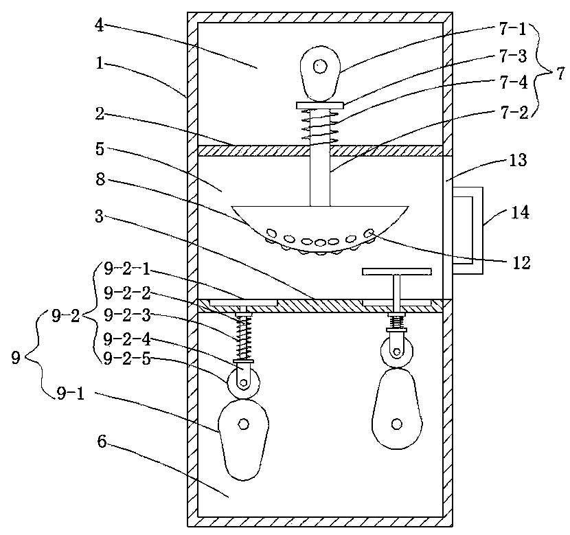
[0022] Such as Figure 1 to 3 As shown, this embodiment provides a kneading device for quickly making dough, which includes a box body 1 in which a baffle 2 and a baffle 3 are sequentially arranged from top to bottom. The baffle 2 and the baffle 3 connect the box The body 1 is divided into upper transmission chamber 4, extrusion chamber 5, and lower transmission chamber 6 from top to bottom. A cam transmission mechanism 7 is provided in the upper transmission chamber 4, and the cam transmission mechanism 7 includes a cam 7-1 and a cam 7. -1 below the push rod 7-2 that penetrates the baffle 2, the top of the push rod 7-2 is provided with a stop 7-3 that cooperates with the cam 7-1, and a winding is provided between the stop 7-3 and the baffle 2. The compression spring 7-4 on the push rod 7-2, the bottom of the push rod 7-2 is provided with an extrusion hammer 8 located in the extrusion chamber 5, and the lower transmission chamber 6 is provided with two cam transmission mechanis...

Embodiment 2

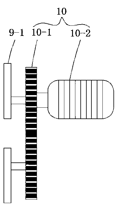
[0025] Such as figure 1 with 2 As shown, this embodiment is further optimized on the basis of Embodiment 1. Specifically, the two cams A9-1 are connected to the same driving mechanism 10, and the driving mechanism 10 includes a gear set 10-1, The gear set 10-1 is composed of two identical gears respectively connected to the corresponding cam A9-1, and one of the gears is connected to the driving motor 10-2.

[0026] In this embodiment, the gear connected to the driving motor drives the other gear to rotate. The two gears are the same, ensuring that the cam A corresponding to the gear can rotate at a constant speed, so that the ejection mechanism corresponding to the cam A moves up and down rhythmically .

Embodiment 3

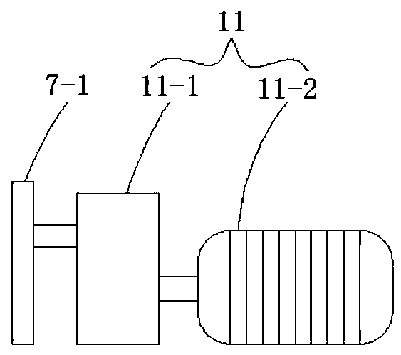
[0028] Such as figure 1 with 3 As shown, this embodiment is further optimized on the basis of Embodiment 1. Specifically, the cam 7-1 is connected with a driving device 11, and the driving device 11 includes a reduction box 11 connected with the cam 7-1. 1. The gearbox 11-1 is connected with a motor 11-2.

[0029] The lower end surface of the squeeze hammer 8 is set as a spherical surface, and a number of uniformly distributed protrusions 12 are provided on the spherical surface.

[0030] The squeezing chamber 5 is provided with a box door 13 and a handle 14 is provided on the box door 13.


PUM


Abstract

The invention discloses a noodle kneading device for quickly making dough, and relates to the technical field of food processing equipment. It is divided into upper transmission chamber, extrusion chamber and lower transmission chamber from top to bottom. The upper transmission chamber is equipped with a cam transmission mechanism. The cam transmission mechanism includes a cam and a push rod that runs through the baffle under the cam. The top of the push rod is set There is a stopper that cooperates with the cam, and a compression spring wound around the push rod is set between the stopper and the baffle, and an extrusion hammer located in the extrusion chamber is arranged at the bottom of the push rod, and two cam transmission mechanisms are arranged in the lower transmission chamber A, the cam transmission mechanism A includes a cam A and an ejection mechanism arranged above the cam A, and the rotational speeds of the two cams A are equal. The present invention has the advantages of simple structure, convenient operation and high production efficiency.

Description

Technical field [0001] The invention relates to the technical field of food processing equipment, and more specifically to a kneading equipment for quickly making dough. Background technique [0002] my country's food processing equipment started in the late 1970s. In the past five years, the food processing equipment industry has developed at an average annual growth rate of 11% to 12%, which is higher than the national economic growth rate during the same period. The product level has reached a new level and has begun to appear. The trend of large-scale, complete sets, and automation, and the appearance of complex transmission and high-tech equipment. It can be said that my country's mechanical production has met the basic domestic needs. [0003] Pasta foods are one of the favorite foods of the masses, and their processing and production have also begun to develop from manual production to mechanization and automation. Some of the existing kneading machines are mixing and kneadin...

Claims


Application Information

Patent Timeline
Patent Type & Authority Applications(China)
IPC IPC(8): A21C7/00A21C3/04
CPCA21C7/00A21C3/04
Inventor 赵元兵
Owner 成都元始信息科技有限公司
Why Eureka
Try Eureka