Dust cup and dust collector provided with dust cup

A technology of dust cup and channel, which is applied in vacuum cleaners, suction filters, household appliances, etc., can solve the problems of large pressure loss of dust-gas separation structure, unreasonable dust-gas separation structure, and low efficiency of dust-gas separation, so as to ensure dust-gas separation Separation efficiency, improvement of dust and gas separation efficiency, effect of improving dust and gas separation efficiency

Active Publication Date: 2018-04-13
JIANGSU MIDEA CLEANING APPLIANCES +1
View PDF7 Cites 4 Cited by
  • Summary
  • Abstract
  • Description
  • Claims
  • Application Information

AI Technical Summary

Problems solved by technology

However, in the related art, the single-cone dust-gas separation structure still has the following problems: (1) The dust-gas separation structure is unreasonable, resulting in low dust-gas separation efficiency; (2) The pressure loss of the dust-gas separation structure is relatively large; (3) With the increase of dust suction, the pressure loss increases, resulting in a rapid drop in suction power, and the unseparated dust particles will accumulate on the filter cotton, resulting in filter cotton clogging, increased pressure loss, and inconvenient cleaning

Method used


Image

  • Dust cup and dust collector provided with dust cup
  • Dust cup and dust collector provided with dust cup
  • Dust cup and dust collector provided with dust cup

Examples


Embodiment Construction

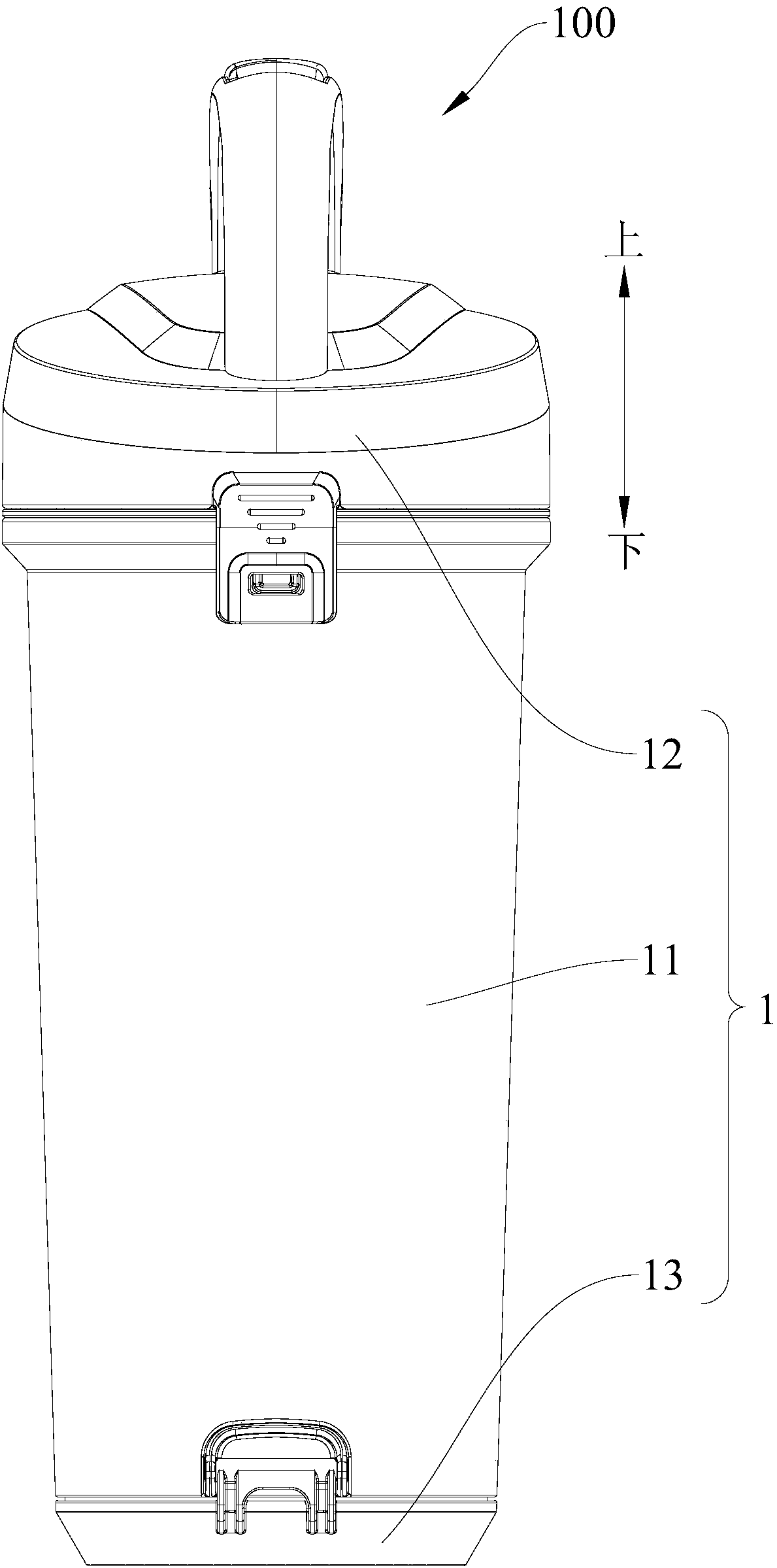
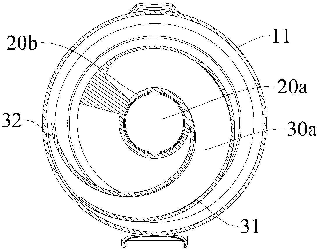
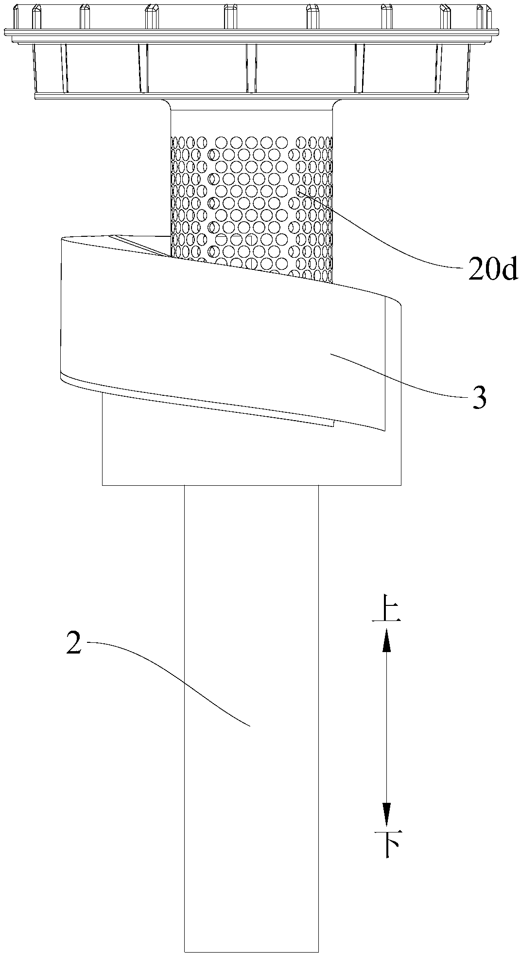
[0031] Embodiments of the present invention are described in detail below, examples of which are shown in the drawings, wherein the same or similar reference numerals designate the same or similar elements or elements having the same or similar functions throughout. The embodiments described below by referring to the figures are exemplary only for explaining the present invention and should not be construed as limiting the present invention.

[0032] In describing the present invention, it is to be understood that the terms "central", "lateral", "upper", "lower", "vertical", "top", "bottom", "inner", "outer", The orientations or positional relationships indicated by "axial", "radial", and "circumferential" are based on the orientations or positional relationships shown in the drawings, and are only for the convenience of describing the present invention and simplifying the description, rather than indicating or implying the It should not be construed as limiting the invention ...


PUM


Abstract

The invention discloses a dust cup and a dust collector provided with the dust cup. The dust cup comprises a dust cup main body, a passage piece and a spiral passage piece, wherein an air inlet is formed in the bottom of the dust cup main body and an air outlet is formed in the top of the dust cup main body; the passage piece is arranged in the dust cup main body; the lower end of the passage piece is connected to the air inlet, and the upper end of the passage piece is connected to the air outlet; a dividing piece is arranged in the passage piece, so that the interior of the passage piece isdivided into an air outlet passage and an air inlet passage which is arranged under the air outlet passage; a plurality of through holes are formed in the sidewall, corresponding to the air outlet passage, of the passage piece, and a communicating port is formed in the sidewall, corresponding to the air inlet passage, of the passage piece; one end of the spiral passage piece is connected to the communicating port and the other end of the spiral passage piece extends upwards in a spiral form along the axial direction of the passage piece until to the sidewall of the dust cup main body; and theother end of the spiral passage piece communicates with the interior of the dust cup main body. The dust cup provided by the invention is simple in structure and convenient for cleaning; and the dust-gas separating efficiency of a dust collection device can be improved, and pressure loss can be reduced.

Description

technical field [0001] The invention relates to the technical field of household appliances, in particular to a dust cup and a vacuum cleaner with the same. Background technique [0002] In the field of dust and gas separation technology, the pressure loss of the multi-cone dust and gas separation structure is relatively large, the structure is relatively complicated, it is inconvenient to clean the dust inside, and it will occupy a large space inside the dust cup. In recent years, some single-cone dust-gas separation structures can achieve the same dust-gas separation efficiency as multi-cone dust-gas separation structures, while the pressure loss is smaller. However, in the related art, the single-cone dust-gas separation structure still has the following problems: (1) The dust-gas separation structure is unreasonable, resulting in low dust-gas separation efficiency; (2) The pressure loss of the dust-gas separation structure is relatively large; (3) With the increase of d...

Claims


Application Information

Patent Timeline
Patent Type & Authority Applications(China)
IPC IPC(8): A47L9/12
CPCA47L9/127
Inventor 赵铠区初斌
Owner JIANGSU MIDEA CLEANING APPLIANCES
Why Eureka
Try Eureka