Gear anti-rusting oil coating equipment
A technology for anti-rust oil and gears, which is applied to coatings and devices that apply liquid to the surface. The effect of rust oil and application of anti-rust oil is fast and convenient, and the use range is wide.
- Summary
- Abstract
- Description
- Claims
- Application Information
AI Technical Summary
Problems solved by technology
Method used
Image

Examples
Embodiment 1
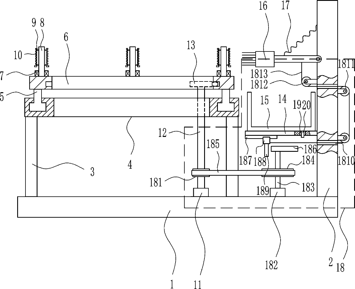
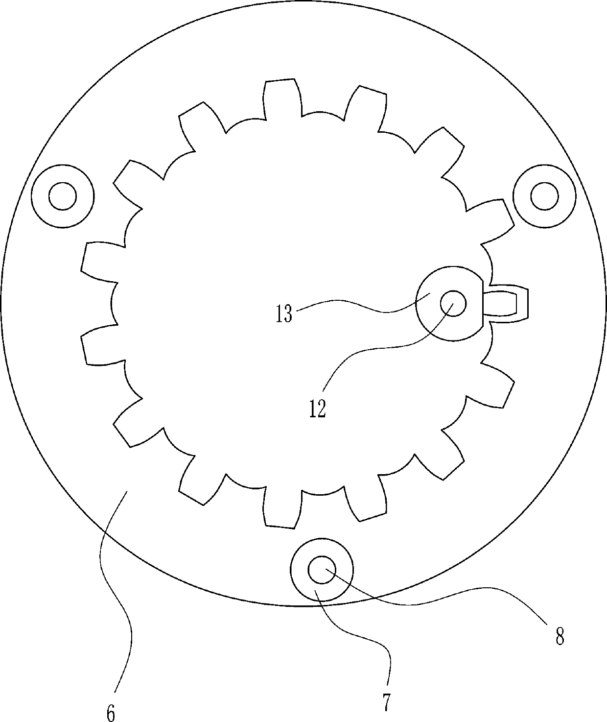
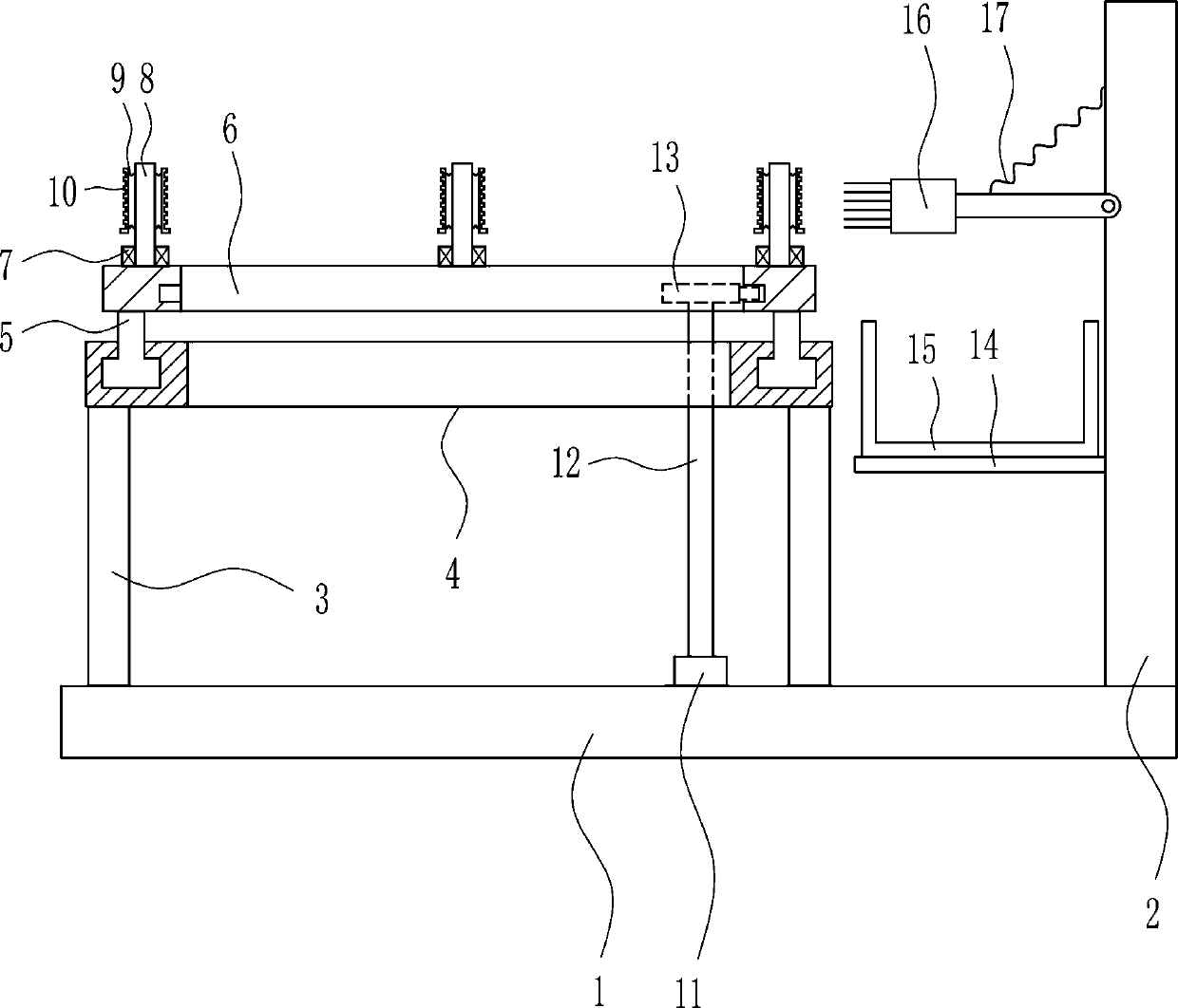
[0029] A gear anti-rust oil coating equipment, such as Figure 1-6 As shown, it includes a bottom plate 1, a mounting plate 2, a pole 3, an annular slide rail 4, a first slider 5, a ring gear 6, a first bearing seat 7, a first rotating shaft 8, a first spring 9, and a clamping plate 10 , the first motor 11, the second rotating shaft 12, the single cone 13, the placement plate 14, the frame body 15, the hair brush 16 and the second spring 17, the upper right side of the base plate 1 is provided with a mounting plate 2, and the upper left side of the base plate 1 is left and right There are support rods 3 symmetrically, the top of the support rod 3 is connected with the ring slide rail 4, the ring slide rail 4 is slidingly connected with the first slider 5, the top of the first slider 5 is connected with the ring gear 6, and the top of the ring gear 6 is uniform There are three first bearing seats 7, and first rotating shafts 8 are arranged in the first bearing seats 7, and firs...
Embodiment 2
[0031] A gear anti-rust oil coating equipment, such as Figure 1-6 As shown, it includes a bottom plate 1, a mounting plate 2, a pole 3, an annular slide rail 4, a first slider 5, a ring gear 6, a first bearing seat 7, a first rotating shaft 8, a first spring 9, and a clamping plate 10 , the first motor 11, the second rotating shaft 12, the single cone 13, the placement plate 14, the frame body 15, the hair brush 16 and the second spring 17, the upper right side of the base plate 1 is provided with a mounting plate 2, and the upper left side of the base plate 1 is left and right There are support rods 3 symmetrically, the top of the support rod 3 is connected with the ring slide rail 4, the ring slide rail 4 is slidingly connected with the first slider 5, the top of the first slider 5 is connected with the ring gear 6, and the top of the ring gear 6 is uniform There are three first bearing seats 7, and first rotating shafts 8 are arranged in the first bearing seats 7, and firs...
Embodiment 3
[0034] A gear anti-rust oil coating equipment, such as Figure 1-6 As shown, it includes a bottom plate 1, a mounting plate 2, a pole 3, an annular slide rail 4, a first slider 5, a ring gear 6, a first bearing seat 7, a first rotating shaft 8, a first spring 9, and a clamping plate 10 , the first motor 11, the second rotating shaft 12, the single cone 13, the placement plate 14, the frame body 15, the hair brush 16 and the second spring 17, the upper right side of the base plate 1 is provided with a mounting plate 2, and the upper left side of the base plate 1 is left and right There are support rods 3 symmetrically, the top of the support rod 3 is connected with the ring slide rail 4, the ring slide rail 4 is slidingly connected with the first slider 5, the top of the first slider 5 is connected with the ring gear 6, and the top of the ring gear 6 is uniform There are three first bearing seats 7, and first rotating shafts 8 are arranged in the first bearing seats 7, and firs...
PUM
 Abstract
Description
Claims
Application Information
 - Generate Ideas
- Intellectual Property
- Life Sciences
- Materials
- Tech Scout
- Unparalleled Data Quality
- Higher Quality Content
- 60% Fewer Hallucinations
Browse by: Latest US Patents, China's latest patents, Technical Efficacy Thesaurus, Application Domain, Technology Topic, Popular Technical Reports.
© 2025 PatSnap. All rights reserved.Legal|Privacy policy|Modern Slavery Act Transparency Statement|Sitemap|About US| Contact US: help@patsnap.com