Full-fabricated concrete beam-column connector based on energy dissipation pieces and shearing resistance pieces and beam-column connecting method

A technology for shear-resistant parts and connectors, which is applied to building components, protective buildings/shelters, earthquake-proof and other directions. Ductile, easy-to-use results

Active Publication Date: 2018-04-13
HUNAN UNIV
View PDF7 Cites 16 Cited by
  • Summary
  • Abstract
  • Description
  • Claims
  • Application Information

AI Technical Summary

Problems solved by technology

However, prefabricated buildings have the problems of troublesome joint reinforcement connection and insufficient internal force transmission.
In order to meet the full transmission of internal forces at the joints, the traditional beam-column connector uses the beam end hinge of the corbel. This structure is a flexible connection, but the building structure is not beautiful enough, and it is not conducive to plastering and leveling in the later stage.

Method used


Image

  • Full-fabricated concrete beam-column connector based on energy dissipation pieces and shearing resistance pieces and beam-column connecting method
  • Full-fabricated concrete beam-column connector based on energy dissipation pieces and shearing resistance pieces and beam-column connecting method
  • Full-fabricated concrete beam-column connector based on energy dissipation pieces and shearing resistance pieces and beam-column connecting method

Examples


Embodiment Construction

[0035] In order to express the object, technical solution and advantages of the present invention more clearly, the present invention will be further introduced below in conjunction with the accompanying drawings.

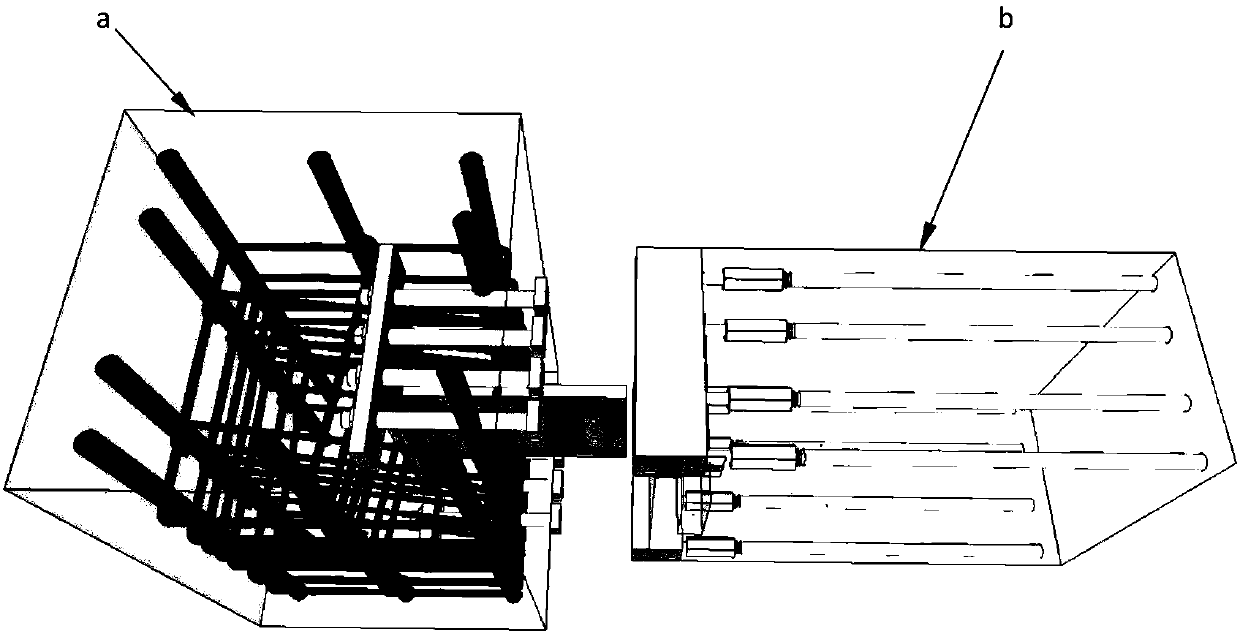
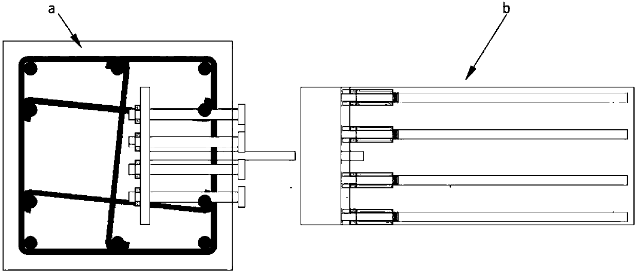
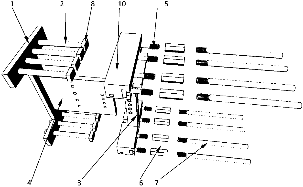
[0036] The invention proposes a beam-to-column connector, which includes three parts, one is the energy-dissipating parts and their anchors embedded in the concrete column, the other is the conversion block embedded in the beam end, and the third is the connecting beam Shear members of the column.

[0037] see details Figure 1-8 As shown, the connector includes energy dissipation parts (2) embedded in precast concrete frame columns, anchors (1), shear parts (4) and conversion blocks (10) embedded in precast concrete frame beam ends and The shear member connection column (3), the energy dissipation member (2) is fixedly connected with the anchor member (1), and the T-shaped connector (5) is installed on the side of the conversion block (10), and the T-shaped conne...


PUM


Abstract

The invention relates to a beam-column connector and a method for connecting beams and columns. The connector comprises energy dissipation pieces (2) pre-embedded in prefabricated concrete frame columns, anchoring pieces (1), shearing resistance pieces (4) and conversion blocks (10) pre-embedded in the ends of prefabricated concrete frame beams; the energy dissipation pieces (2) are fixedly connected with the anchoring pieces (1) through bolts, T-shaped connecting heads (5) are mounted on the side faces of the conversion blocks (10), and the T-shaped connecting heads (5) and steel bars (7) inthe beams are connected through sleeves (6); beam end clamping grooves (9) are formed in the conversion blocks (10), and the beam end clamping grooves (9) and column end protrusions (8) are mutually fastened, so that quick connecting of tensile steel bars (compression steel bars) is achieved; the shearing resistance pieces (4) at the beam ends penetrate through column end shearing resistance piececonnection columns (3), the shearing resistance pieces (4) and the column end shearing resistance piece connection columns (3) are connected by inserting bolts into screw holes in the side faces, andthrough the device, the beams and the columns are firmly connected. The beam-column connector can not only transmit shearing force, but also can transmit beam end bending moment, and the beam-columnconnector is more close to a cast-in-place joint; and in addition, the beam-column connector applies a ductility material, so that ductility of the beam-column connector under action of the earthquakeload is increased.

Description

technical field [0001] The invention relates to the field of construction engineering, in particular to a beam-column connector and a method for connecting beams and columns. Background technique [0002] Prefabricated buildings refer to buildings assembled on site with prefabricated components. The advantage of this kind of building is that it is fast in construction, less restricted by climatic conditions, saves labor and can improve the quality of the building. The components can be industrialized in the factory, and the construction site can be installed directly, which is convenient and fast, and can shorten the construction period. . However, prefabricated buildings have the problems of troublesome node reinforcement connection and insufficient internal force transmission. In order to allow the joints to fully transmit the internal force, the traditional beam-column connector adopts the beam end hinge of the corbel. This structure is a flexible connection, but the bu...

Claims


Application Information

Patent Timeline
Patent Type & Authority Applications(China)
IPC IPC(8): E04B1/20E04B1/21E04B1/98E04H9/02
CPCE04B1/20E04B1/21E04H9/021
Inventor 周云胡翔陈太平赵瑜李紫玮
Owner HUNAN UNIV
Why Eureka
Try Eureka