Gear floating type raise-boring machine

A raise drilling rig, floating type technology, which is applied in the direction of reverse drilling, drill bit, vertical well equipment, etc., can solve the problems of low rock breaking efficiency, inability to use flexibly, and the angle of the hob cannot be adjusted, and achieves ingenious structural design and use. Flexibility, improved rock breaking efficiency and smoothness

Inactive Publication Date: 2018-04-13
JIANGSU HEXIN PETROLEUM MACHINERY
View PDF5 Cites 9 Cited by
  • Summary
  • Abstract
  • Description
  • Claims
  • Application Information

AI Technical Summary

Problems solved by technology

The drill bit in the raise drilling rig is the most important part of the whole mechanism. Generally, the drill bit includes a cutter head, a tool seat, and a hob. The tool seat is installed on the cutter head, and the hob is installed on the tool seat. The distribution and structure of the hob It has a great impact on the efficiency and stability of rock breaking. The existing tool holders are fixedly connected to the cutter head, and the positions of the cutter holders are pre-distributed. Self-correct the position of the tool holder according to the rock-breaking surface; in addition, the existing hob has a cylindrical structure with integrated grinding ribs on the side of the cylindrical structure, but such an integrated hob will be hit after long-term operation Damaged or severely worn, so the entire hob is scrapped, and a new hob needs to be disassembled and reinstalled, which affects operating efficiency and operating costs; the angle of the hob in the prior art cannot be adjusted according to the rock breaking surface , resulting in inconsistent contact between the hob and the rock-breaking surface, resulting in low rock-breaking efficiency

Method used


Image

  • Gear floating type raise-boring machine
  • Gear floating type raise-boring machine
  • Gear floating type raise-boring machine

Examples


Embodiment Construction

[0027] The content of the present invention will be further described in detail below in conjunction with the accompanying drawings.

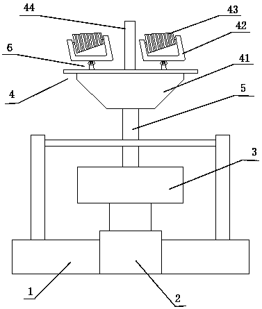
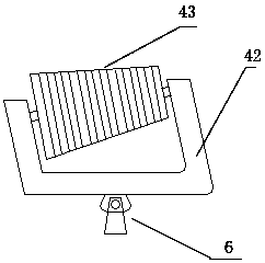
[0028] Such as figure 1 and 2 As shown, a gear-floating type raise drilling machine includes a base support 1 , a telescopic drive mechanism 2 , a rotary drive mechanism 3 , a drill pipe 5 , and a drill bit 4 . The telescopic driving mechanism 2 is installed on the base support 1 . The rotary drive mechanism 3 is installed on the upper end of the telescopic drive mechanism 2 . The telescoping drive mechanism 2 controls the rotation drive mechanism 3 to move up and down. The bottom of the drill rod 5 is installed on the rotary drive mechanism 3 . The rotation drive mechanism 3 controls the rotation of the drill rod 5 . The drill bit 4 is installed at the upper end of the drill rod 5 . The drill bit 4 includes a cutter head 41 , a cutter seat 42 , a hob 43 and a probe rod 44 . The cutter head 41 is installed on the upper end of the drill r...


PUM


Abstract

The invention discloses a gear floating type raise-boring machine. The gear floating type raise-boring machine comprises a base bracket, a telescopic driving mechanism, a rotating driving mechanism, adrill pipe and a drill bit. The bottom of a cutter holder is installed on a cutterhead through a rotating movable mechanism. A hob comprises a carrier piece, a plurality of floating gears and a plurality of elastomers. The carrier piece is of a circular-table-shaped structure. A plurality of clamping-connecting sliding grooves are formed around the carrier piece and distributed evenly to form anannular structure in a surrounding mode. The multiple elastomers are installed in the clamping-connecting sliding grooves. The multiple floating gears are connected into the clamping-connecting sliding grooves in a clamped mode and abut against the elastomers in a pressing mode to make the elastomers be compressed under force. The outer side of the periphery of the carrier piece is evenly connected with the multiple floating gears in a clamped mode. According to the gear floating type raise-boring machine, the floating gears can be matched with the broken rock surface, so that the rock breaking efficiency and smoothness are improved.

Description

technical field [0001] The invention relates to a gear floating type raise drilling machine. Background technique [0002] At present, raise drilling rigs are mainly used in industries such as vertical shafts, inclined shafts, surge shafts, ventilation shafts and drainage shafts in hydropower projects, ventilation shafts in railway construction, and mine slag shafts. The drill bit in the raise drilling rig is the most important part of the whole mechanism. Generally, the drill bit includes a cutter head, a tool seat, and a hob. The tool seat is installed on the cutter head, and the hob is installed on the tool seat. The distribution and structure of the hob It has a great impact on the efficiency and stability of rock breaking. The existing tool holders are fixedly connected to the cutter head, and the positions of the cutter holders are pre-distributed. Self-correct the position of the tool holder according to the rock-breaking surface; in addition, the existing hob has a ...

Claims


Application Information

Patent Timeline
Patent Type & Authority Applications(China)
IPC IPC(8): E21B10/43E21B10/54E21D3/00
CPCE21B10/43E21B10/54E21D3/00
Inventor 赵钧羡李波吴敏段隆臣刘志强胡郁乐胡新丽
Owner JIANGSU HEXIN PETROLEUM MACHINERY
Why Eureka
Try Eureka