
Nozzle ring for turbocharger

A technology of turbocharger and nozzle ring, applied in machine/engine, stator, engine components, etc., can solve the problems of inconsistent starting time and angular rotation rate, reduced blade rotation synchronization, affecting engine performance, etc. Achieve the effect of increasing the length and area of ​​contact and mating, simplifying the processing and assembly process, and achieving good rotation consistency and synchronization

Active Publication Date: 2018-04-13
江西省萍乡市三善机电有限公司
View PDF6 Cites 0 Cited by
  • Summary
  • Abstract
  • Description
  • Claims
  • Application Information

AI Technical Summary

Problems solved by technology

[0003] The existing turbocharger variable section nozzle ring still has the following problems in operation: the shift fork drives the shift fork, and the shift fork drives the blades to swing. The radial positioning of the fork plate rotation is achieved by the sliding fit of the guide wheels arranged at fixed intervals between the guide wheel pins on the mounting plate. After working for a certain period of time, the wear gap between each set of arc-shaped grooves and the guide wheel increases, and the radial runout of the fork plate rotation increases, resulting in an increase in the rotation angle error of the blade driven by the fork plate to swing, and the blade rotates The initial time of the fork is inconsistent with the rate of angular rotation, resulting in a reduction in the synchronization of the blade rotation; and one end of the fork is fixedly connected to the blade, and the other end of the fork is embedded in a cylindrical groove on the fork plate. When the disc rotates, because the contact gap between the cylindrical groove and the other end of the shift fork is not uniform, after a certain period of work, the swing of the shift fork will vary from fast to slow, causing the blades to not rotate synchronously.
The existence of these two problems will cause uneven air intake per unit time, thus affecting the working performance of the engine

Method used


Image

  • Nozzle ring for turbocharger
  • Nozzle ring for turbocharger
  • Nozzle ring for turbocharger

Examples


Embodiment Construction

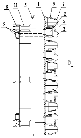
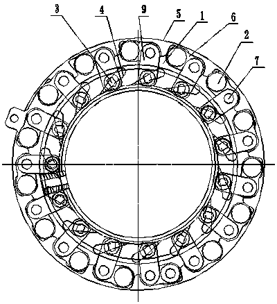
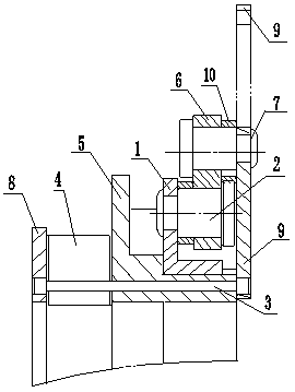
[0019] exist figure 1 , figure 2 , image 3 and Figure 4 Among them, a nozzle ring for a turbocharger includes a lining plate 8, a mounting plate 5 and a shift fork plate 1, and five spacer shafts 11 are arranged between the lining plate and the mounting plate, and the lining plate and the mounting plate There are several blades 4 (fifteen blades in this embodiment) arranged at intervals between the disks. The blades are pointed pear-shaped. Under the action, it can rotate concentrically (left and right) around the mounting plate. The original plate-shaped fork plate is designed as a T-shaped bushing, and the original plate-shaped fork plate is made into an integral T with flange sleeve. The shape of the fork plate (such as Figure 4 shown), so as to increase the axial matching distance between the fork plate and the mounting plate, and increase the contact length and area of ​​the fork plate and the outer surface of the mounting plate, so that the rotation stability of t...


PUM


Abstract

The invention discloses a nozzle ring for a turbocharger. The nozzle ring comprises a lining plate, a mounting disc and a shifting fork disc, fixed distance shafts and vanes are arranged between the lining plate and the mounting disc at intervals, and the shifting fork disc is mounted on the outer circle of the mounting disc in a sleeving mode and can rotate around the mounting disc to do concentric rotation; and the shifting fork disc is movably connected with one ends of connecting plates through pin shafts in a spaced mode, the other ends of the connecting plates are movably connected withone ends of shifting forks through pin shafts, the other ends of the shifting forks are fixedly connected with one ends of vane shafts, and the other ends of the vane shafts penetrate through the mounting disc and are fixedly connected with the vanes and fixed to the lining plate. According to the nozzle ring for the turbocharger, the shifting fork disc and the outer circle of the mounting disc are directly matched for radial positioning, cylindrical grooves are not required to be formed in the shifting fork disc to be matched with one ends of the shifting forks for radial positioning of the shifting fork disc, but the shifting forks are driven by adopting the mode of rivet-connected connecting plates, the structure is more compact, machining is more simple and convenient, the machining accuracy is higher, and vane synchronization is more consistent.

Description

technical field [0001] The present invention relates to a turbocharger, in particular to a nozzle ring for a turbocharger. Background technique [0002] As we all know, a turbocharger is a product used to boost the air intake of an internal combustion engine and improve the working efficiency of the internal combustion engine. It is driven by the exhaust gas discharged from the internal combustion engine. The vanes at the compressor end of the turbocharger installed on the shaft on the intake pipe of the internal combustion engine rotate the intake air to increase the intake pressure, improve the working conditions of the internal combustion engine, and increase the power of the internal combustion engine. Among them, the blades in the variable section nozzle ring It is a component that changes the size of the exhaust section by rotating at a certain angle, thereby adjusting the exhaust pressure of the turbocharger, controlling the speed of the turbocharger, and then control...

Claims


Application Information

Patent Timeline
Patent Type & Authority Applications(China)
IPC IPC(8): F01D9/04F01D17/16F02B37/24
CPCF01D9/041F01D17/16F02B37/24F05D2220/40Y02T10/12
Inventor 欧阳鹏志潘保良黎书珍
Owner 江西省萍乡市三善机电有限公司
Learn More