
Heat-dissipating structure of cement kiln

A heat dissipation structure, cement kiln technology, applied in lighting and heating equipment, furnace cooling, furnace, etc., can solve the problems of refractory brick falling off, waste heat cannot be recovered, violation, etc., and achieve the effect of improving production efficiency

Active Publication Date: 2018-04-13
吉林金隅冀东环保科技有限公司
View PDF5 Cites 1 Cited by
  • Summary
  • Abstract
  • Description
  • Claims
  • Application Information

AI Technical Summary

Problems solved by technology

[0005] At present, the mainstream measure to cool the cylinder is the blowing method of the axial flow fan. There is also a newest technical design. We call it the design because no factory has adopted it in real time. This is from Guangzhou Ocean University. A utility model patent, which adopts the method of winding cold water pipes on the cylinder to cool down and recover waste heat. Through the actual comparison on the spot and the analysis of computer models, this water cooling method is more serious than the damage caused by rainwater pouring on the cylinder, and not only cannot be recycled The waste heat will also increase the large area of ​​refractory bricks falling off inside the cement kiln shell. The theoretical design is an ideal design that violates natural science and practical application, and the biggest disadvantage of water cooling is that the water must flow continuously. A cement factory, even if Regardless of the danger of burning through the cylinder after falling bricks, it is impossible to have such a large water source for its use

Method used


Image

  • Heat-dissipating structure of cement kiln
  • Heat-dissipating structure of cement kiln
  • Heat-dissipating structure of cement kiln

Examples


Embodiment Construction

[0029] Below, refer to the attached Figure 1 to Figure 2 As shown, a heat dissipation structure of a cement kiln includes: an air inlet 101, an air outlet 102 and a Venturi heat dissipation pipe 103;

[0030] Further, the number of the air inlets 101 is at least four groups, and the number of the air outlets 102 is at least four groups;

[0031] As an example, the shape of the air inlet 101 and the air outlet 102 is set as an oblate arc shape;

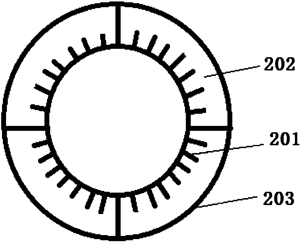
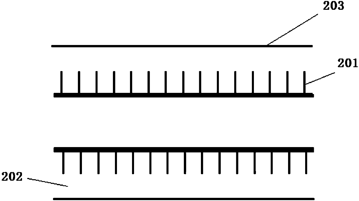
[0032] Further, the Venturi heat dissipation pipe 103 is set in the shape of a cylinder, wrapped outside the cement kiln cylinder, including: a heat sink layer 201, a Venturi ventilation heat dissipation layer 202 and an external protective layer 203; the heat sink layer 201 is closely attached to The cement kiln shell is set, and the Venturi ventilation heat dissipation layer 202 is located between the heat dissipation sheet layer 201 and the outer protective layer 203;

[0033] As an example, the outer protective layer 203 is made...


PUM


Abstract

A heat-dissipating structure of a cement kiln comprises an air inlet, an air outlet and a Venturi heat-dissipating pipeline; the Venturi heat-dissipating pipeline adopts a cylinder shape, is wrapped outside a cement kiln cylinder body and comprises a heat-dissipating sheet layer, a Venturi ventilating and heat-dissipating layer and an outer protective layer; the heat-dissipating sheet layer abutsagainst the cement kiln cylinder body; the Venturi ventilating and heat-dissipating layer is positioned between the heat-dissipating sheet layer and the outer protective layer; the air inlet is formedat one end of the Venturi heat-dissipating pipeline near one side of an igniter and on the tail part of the cement kiln; and the air outlet is formed at the other end of the Venturi heat-dissipatingpipeline near one side of a secondary air pipe and on the head part of the cement kiln, and communicates with the secondary air pipe. The heat-dissipating structure of the cement kiln overcomes the defects that the kiln cylinder body is difficult to cool and heat is lost; and due to circulating cooling of the air, local thermal expansion and cold contraction are avoided, malignant production accidents caused by the fact that a refractory brick in the kiln cylinder body falls off under water cooling are avoided, a certain silencer effect is achieved, and the noise generated by the kiln cylinderbody in the production process is greatly reduced.

Description

technical field [0001] The patent of the present invention relates to the technical field of dry process cement production equipment, in particular to a heat dissipation structure of a cement kiln. Background technique [0002] Dry process cement has been gradually introduced into my country from Japan since the 1980s. The firing stage in the new dry process is the core technology. New raw materials, fuel pre-homogenization technology and energy-saving grinding technology and equipment are adopted. Control to realize the automation and high efficiency, high quality, low consumption and environmental protection of the cement production process; [0003] The key sign of the new dry process sintering technology is that the sintering equipment adopts a new dry process cement kiln; the new dry process cement kiln is a replacement kiln type of the old dry process cement kiln. The new dry-process cement kiln is much superior to the shaft kiln, dry-process hollow kiln, Lipoer kiln a...

Claims


Application Information

Patent Timeline
IPC IPC(8): F27B7/38F27D9/00
CPCF27B7/38F27D9/00F27D2009/0005
Inventor 王秀坤
Owner 吉林金隅冀东环保科技有限公司
Learn More