
Resonant scanning mirror, scanning method, scanning angle measurement method and resonant scanning mirror processing method

A scanning mirror and resonant technology, applied in the field of environmental perception, can solve the problems that the resonant scanning mirror with large aperture and large scanning angle cannot be realized, affects the application of the resonant scanning mirror, and the flatness of the mirror is difficult to guarantee, so as to reduce the installation cost , installation is convenient and simple, and the effect of reducing distortion

Inactive Publication Date: 2018-04-13
HESAI TECH CO LTD
View PDF6 Cites 14 Cited by
  • Summary
  • Abstract
  • Description
  • Claims
  • Application Information

AI Technical Summary

Problems solved by technology

The mirror size of the resonant scanning mirror made by MEMS technology is generally small, usually 1-2mm in diameter, and the flatness of the mirror surface is difficult to guarantee, and it is impossible to realize the resonant scanning mirror with large aperture and large scanning angle, which affects the resonant scanning mirror. Applications in LiDAR for Long Range Detection

Method used


Image

  • Resonant scanning mirror, scanning method, scanning angle measurement method and resonant scanning mirror processing method
  • Resonant scanning mirror, scanning method, scanning angle measurement method and resonant scanning mirror processing method
  • Resonant scanning mirror, scanning method, scanning angle measurement method and resonant scanning mirror processing method

Examples


Embodiment Construction

[0035] In the existing product scheme, the MEMS technology is used to make the resonant scanning mirror. The size of the mirror surface is generally small, usually 1-2mm in diameter. Therefore, it affects the application of the resonant scanning mirror in the long-distance detection laser radar.

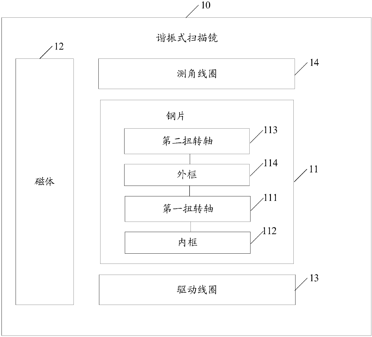
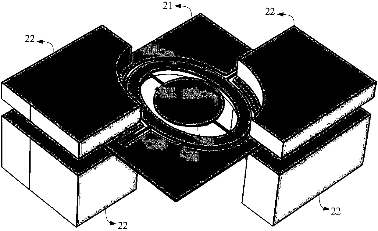
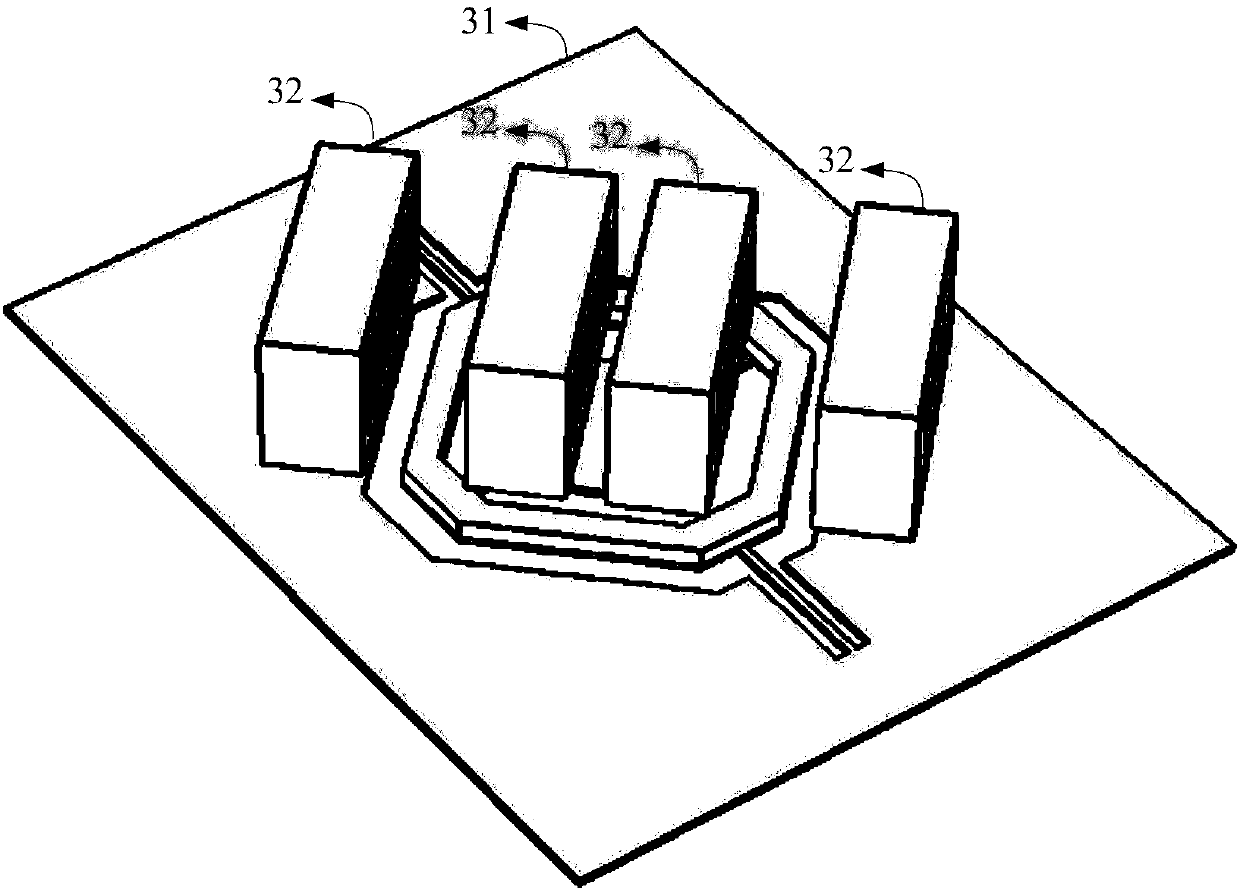
[0036] The embodiment of the present invention provides a resonant scanning mirror based on the steel sheet processing technology. By setting the driving coil and the angle measuring coil on the steel sheet, on the one hand, the driving coil drives the inner frame to rotate, and the light beam is reflected by the smooth surface of the inner frame. , can realize large-caliber and large-angle scanning at a lower cost; on the other hand, the measurement of the scanning angle is realized by the angle measuring coil, which simplifies the method of piezoresistive or capacitive angle measurement used in the MEMS process, and the process Simple and low cost.

[0037] In order to make the ab...


PUM


Abstract

The invention relates to a resonant scanning mirror, a scanning method, a scanning angle measurement method and a resonant scanning mirror processing method. The resonant scanning mirror comprises a steel sheet, a magnet, a driving coil and an angle measurement coil, wherein the steel sheet comprises a first torsion shaft and an inner frame connected with the first torsion shaft, the inner frame is provided with a smooth surface suitable for beam reflection, the magnet is suitable for generating the single-directed magnetic field at the level of the steel sheet, the driving coil is arranged inthe inner frame of the steel sheet and is suitable for bearing the force in the magnetic field generated by the magnet to drive the inner frame to rotate when a driving current is inputted, and the angle measurement coil is arranged in the inner frame of the steel sheet and is suitable for measuring a scanning angle of the inner frame. The resonant scanning mirror is advantaged in that on one hand, large-aperture and large-angle scanning can be realized with relatively low cost, on the other hand, a piezoresistive or capacitance measurement angle measurement realization method in the MEMS process is simplified, the process is simple, and cost is low.

Description

technical field [0001] The embodiments of the present invention relate to the technical field of environment perception, and in particular to a resonant scanning mirror, a scanning method, an angle measurement method and a processing method. Background technique [0002] With the continuous advancement of autonomous driving technology, resonant scanning mirror (ie galvanometer) lidar is regarded as an important technical route in the solid-state lidar solution. The resonant scanning mirror can be used to scan the light beam emitted by the light source, and is widely used in micro-projection display systems. Compared with traditional projection imaging, the resonant scanning mirror can not only be used for scanning when laser pulses are emitted, but also can be used for receiving and reflecting echo signals of laser pulses. [0003] For the long-distance detection laser radar system, the optical aperture of the resonant scanning mirror is required to have a large size when r...

Claims


Application Information

Patent Timeline
Patent Type & Authority Applications(China)
IPC IPC(8): G02B26/10G02B26/08G01B11/26
CPCG01B11/26G02B26/085G02B26/10
Inventor 叶良琛毛胜平张子夏向少卿李一帆
Owner HESAI TECH CO LTD
Learn More