
A combined knob lever switch device

A lever switch and combined technology, which is applied in the field of combined knob and lever switch devices, can solve the problems of poor switch feel, difficult user satisfaction, and difficult assembly, so as to reduce assembly difficulty and production cost, and reduce the risk of error Effect

Active Publication Date: 2019-02-15
扬州航盛科技有限公司
View PDF3 Cites 0 Cited by
  • Summary
  • Abstract
  • Description
  • Claims
  • Application Information

AI Technical Summary

Problems solved by technology

[0002] The control panel of various electrical equipment in the car body is generally equipped with a plurality of key switches, knob switches, universal levers or other forms of switches for the operation of the internal components of the controller. If the aforementioned switches are simply arranged in sequence, the A control panel with a large surface area is required, and the structure is not compact enough, and the overall design style of the panel is relatively boring and monotonous, which is difficult to satisfy users. Therefore, combining multiple switches into one structure is a solution to the aforementioned problems. one
But the combined key switch device also has defects: the conventional combined switch device mainly utilizes the combination of electronic devices such as rotary switch and universal switch to realize three functions of knob, button and universal lever. Yes: a large number of electronic devices are required, the cost is high, and the structure is not compact enough, the volume is large, the switch feels poor, there is a threading process in the assembly process, the requirements for the production line workers are high, and the assembly is difficult. risk of assembly errors

Method used


Image

  • A combined knob lever switch device
  • A combined knob lever switch device
  • A combined knob lever switch device

Examples


Embodiment Construction

[0032] Below in conjunction with accompanying drawing, the present invention is further described:

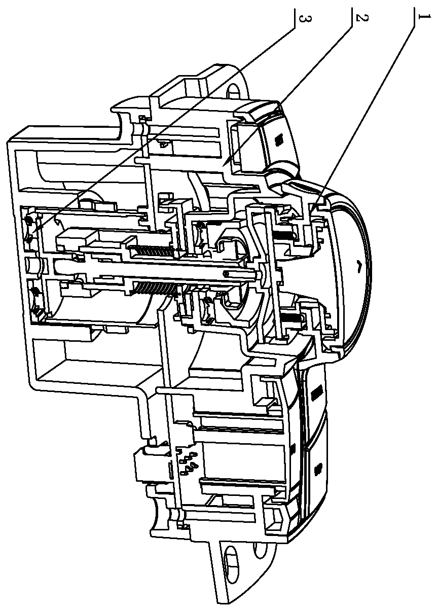
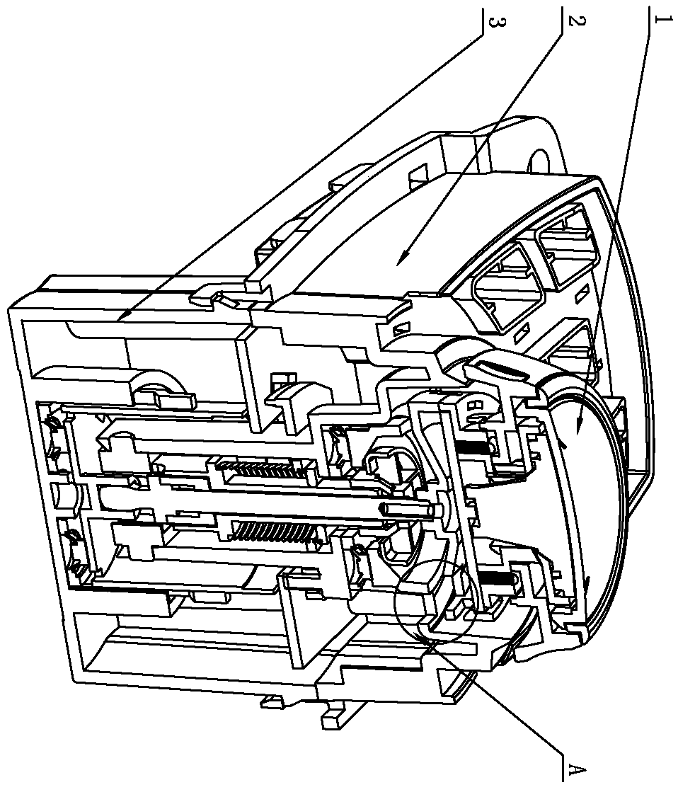
[0033] Such as Figure 1-14 A combined knob and lever switch device shown includes a knob structure 1 and a pressing structure 3, and a lever structure 2 is connected between the knob structure 1 and the pressing structure 3;

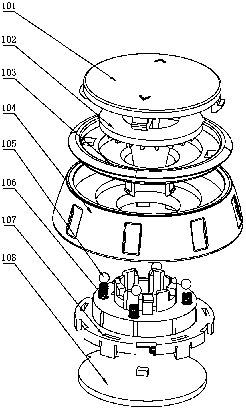
[0034] The knob structure 1 includes a circuit board 108 on which a photoelectric switch 110 is installed, the circuit board 108 is connected with the knob bracket 107, the knob bracket 107 is provided with a knob cover 104, and the knob cover 104 is provided with a light-shielding component 109, a light-shielding component 109 The photoelectric switch one 110 is turned on or off by turning the knob cover 104;

[0035] The lever structure 2 includes a main circuit board 206, a universal buckle 209 and a lever sleeve 208 arranged in the housing 202. The upper surface of the main circuit board 206 is provided with a photoelectric switch group 1 214 and a ph...


PUM


Abstract

The present invention discloses a combined knob lifting lever switch device which is on an automobile operation and control panel and in the switch device field. The combined knob lifting lever switchdevice comprises a knob structure and a pressing structure, a lifting lever structure is connected between the knob structure and the pressing structure, and the knob structure comprises a circuit board equipped with an optoelectronic switch 1. The circuit board is connected with a knob support, a knob rotating cover sleeves the knob support, and a shading part is arranged in the knob rotating cover. The optoelectronic switch is arranged on the circuit board, by combining the knob structure, the lifting lever structure and the pressing structure together, when the rotation, stirring and pressing operations are carried out, the structural members are utilized to generate the displacement, so that the optoelectronic switch switches between the connection and disconnection, and accordingly,the motion states of the structures are identified, a motion relationship is converted into an electric signal, the purpose of integrating the various switches on an operation and control panel is achieved, and the assembly difficulty and the production cost are reduced substantially, and the risk of making mistakes at assembly is reduced. The combined knob lifting lever switch device of the present invention can be used on an electrical equipment operation and control panel in an automobile.

Description

technical field [0001] The invention relates to a switch device, in particular to a combined rotary knob switch device used on the control panel of electric equipment in a car. Background technique [0002] The control panel of various electrical equipment in the car body is generally equipped with a plurality of key switches, knob switches, universal levers or other forms of switches for the operation of the internal components of the controller. If the aforementioned switches are simply arranged in sequence, they will A control panel with a large surface area is required, and the structure is not compact enough, and the overall design style of the panel is relatively boring and monotonous, which is difficult to satisfy users. Therefore, combining multiple switches into one structure is a solution to the aforementioned problems. one. But the combined key switch device also has defects: the conventional combined switch device mainly utilizes the combination of electronic de...

Claims


Application Information

Patent Timeline
Patent Type & Authority Patents(China)
IPC IPC(8): H01H25/00
CPCH01H25/00
Inventor 王利新倪超束敏星王艳
Owner 扬州航盛科技有限公司
Learn More