Check patentability & draft patents in minutes with Patsnap Eureka AI!

Optimal configuration method and system for synchronous phasor measurement unit

A technology of synchrophasor measurement and optimized configuration, applied in system integration technology, information technology support system, electrical components, etc., can solve the problem of insufficient research on disturbance source positioning, and achieve the effect of ensuring safe and stable operation

Active Publication Date: 2018-04-13
POWER DISPATCHING CONTROL CENT OF GUANGDONG POWER GRID CO LTD +1
View PDF8 Cites 0 Cited by
  • Summary
  • Abstract
  • Description
  • Claims
  • Application Information

AI Technical Summary

Problems solved by technology

[0004] Existing studies mostly focus on the forced oscillation caused by the power disturbance of the prime mover, but the research on the mechanism, influencing factors and location of the disturbance source on the load side is not thorough enough.
There are few monitoring measures specifically aimed at the load-side forced oscillation. Therefore, it is urgent to provide a PMU configuration method that can be used to locate the disturbance source of the load-side forced oscillation to make up for the above technical gaps.

Method used


Image

  • Optimal configuration method and system for synchronous phasor measurement unit
  • Optimal configuration method and system for synchronous phasor measurement unit
  • Optimal configuration method and system for synchronous phasor measurement unit

Examples


Embodiment Construction

[0015] In order to make the object, technical solution and advantages of the present invention clearer, the present invention will be further described in detail below in conjunction with the accompanying drawings and embodiments. It should be understood that the specific embodiments described here are only used to explain the present invention, not to limit the present invention.

[0016] Unless otherwise defined, all technical and scientific terms used herein have the same meaning as commonly understood by one of ordinary skill in the technical field of the invention. The terms used herein in the description of the present invention are for the purpose of describing specific embodiments only, and are not intended to limit the present invention. As used herein, the term "and / or" includes any and all combinations of one or more of the associated listed items.

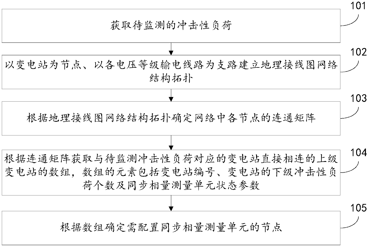
[0017] Such as figure 1 As shown, a method for optimizing the configuration of a synchrophasor measurement unit pro...


PUM


Abstract

The invention relates to an optimal configuration method for a synchronous phasor measurement unit, which comprises the steps of acquiring an impact load to be monitored; establishing a geographic wiring diagram network structure topology by taking substations as nodes and taking power transmission lines of different voltage levels as branches; determining a connection matrix of each node in the network according to the geographic wiring diagram network structure topology; acquiring an array of upper-level substations directly connected with a substation corresponding to the impact load to bemonitored according to the connection matrix, wherein elements of the array comprise a substation serial number, the number of lower-level impact loads of the substation and state parameters of the synchronous phasor measurement unit; and determining nodes requiring configuration of the synchronous phasor measurement unit according to the array. The invention further provides an optimal configuration system for the synchronous phasor measurement unit. According to the optimal configuration method and system for the synchronous phasor measurement unit, the number of the synchronous phasor measurement units required to be configured can be reduced to be maximum extent while realizing accurate positioning and monitoring for a load-side compulsive oscillation and disturbance source in an electric power system.

Description

technical field [0001] The invention relates to the field of power system safety and stability, in particular to a method and system for optimizing the configuration of a synchronized phasor measurement unit for locating a load-side forced oscillation disturbance source. Background technique [0002] With the increasing scale of the power grid, forced power oscillation occurs many times in the actual power grid, seriously affecting the safe and stable operation of the power grid. The continuous periodic load disturbance in the power system will cause the forced oscillation of the power system. When the disturbance frequency is the same as or close to the natural oscillation frequency of the power system, resonance will occur. The forced oscillation of the power system will reach the maximum value, which is manifested as a violent swing of the rotor angle between units. Large fluctuations in power transmitted by transmission lines. The key to the low-frequency oscillation of...

Claims


Application Information

Patent Timeline
Patent Type & Authority Applications(China)
IPC IPC(8): H02J3/00
CPCH02J3/00H02J2203/20Y02E40/70Y02E60/00Y04S10/00Y04S10/22
Inventor 伍双喜吴国炳徐衍会宫晓珊杨银国钱峰刘俊磊段秦刚
Owner POWER DISPATCHING CONTROL CENT OF GUANGDONG POWER GRID CO LTD
Features
  • R&D
  • Intellectual Property
  • Life Sciences
  • Materials
  • Tech Scout
  • Unparalleled Data Quality
  • Higher Quality Content
  • 60% Fewer Hallucinations
Learn More