Constant-pressure hydraulic control valve

A technology for hydraulic control valves and constant pressure devices, which is applied in the direction of lifting valves, safety valves, balance valves, etc., and can solve problems such as damage to force control valves and water pipes, and achieve increased contact area, good sealing, and damage prevention. Effect

Inactive Publication Date: 2018-04-17
温州诚博阀门有限公司
View PDF0 Cites 3 Cited by
  • Summary
  • Abstract
  • Description
  • Claims
  • Application Information

AI Technical Summary

Problems solved by technology

[0003] Since the pressure of the water body in the water pipe is related to the output of the water body, when the pressure of the water body is too high, it is easy to cause damage to the water pipe, and the hydraulic control valve is connected to the water pipe, which may cause damage to the force control valve

Method used


Image

  • Constant-pressure hydraulic control valve
  • Constant-pressure hydraulic control valve
  • Constant-pressure hydraulic control valve

Examples


Embodiment Construction

[0017] The following will clearly and completely describe the technical solutions in the embodiments of the present invention with reference to the accompanying drawings in the embodiments of the present invention. Obviously, the described embodiments are only some, not all, embodiments of the present invention. Based on the embodiments of the present invention, all other embodiments obtained by persons of ordinary skill in the art without making creative efforts belong to the protection scope of the present invention.

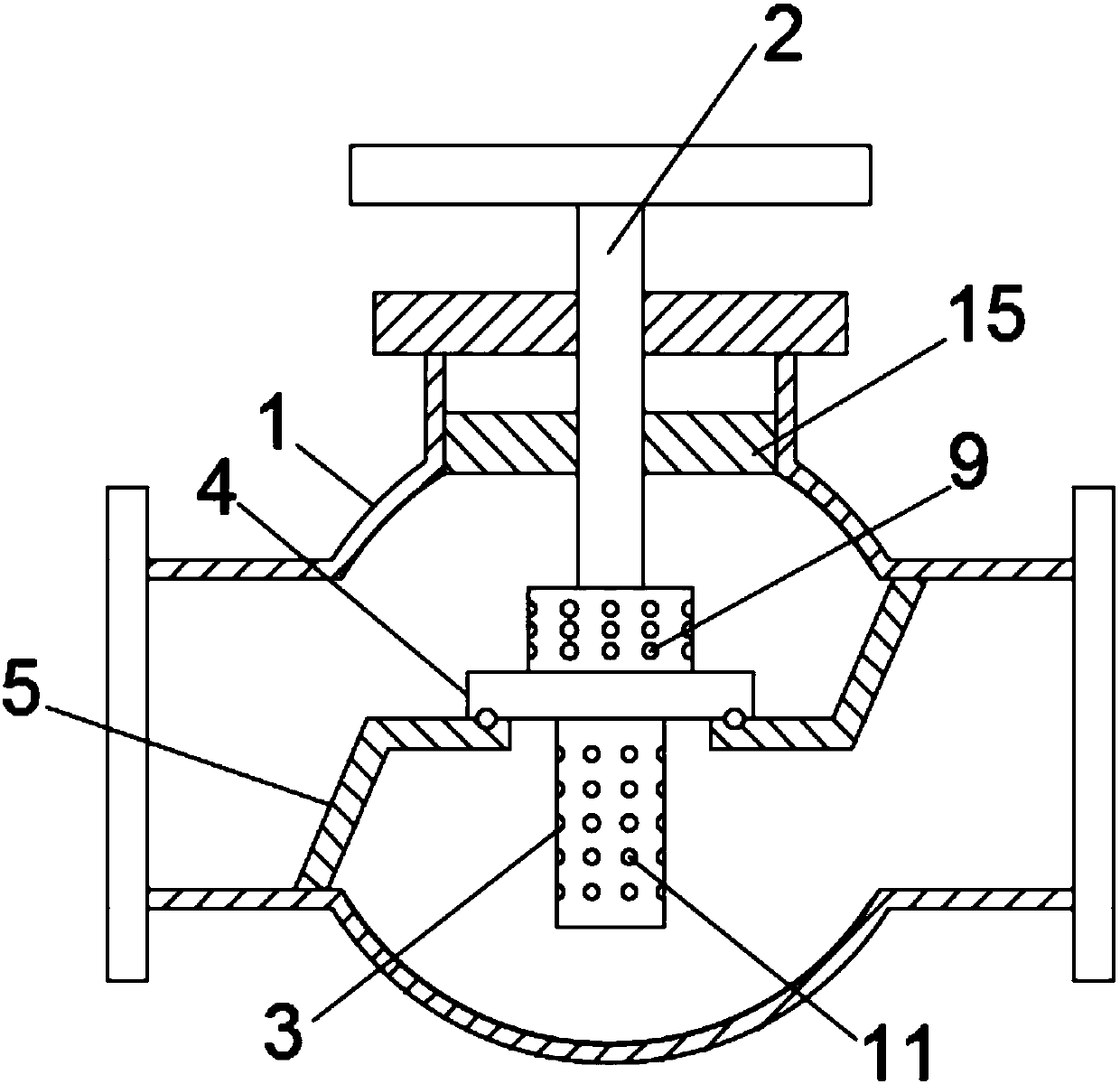
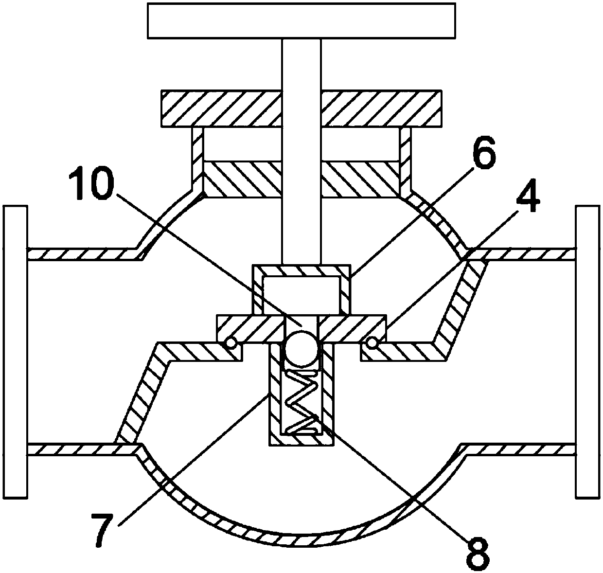
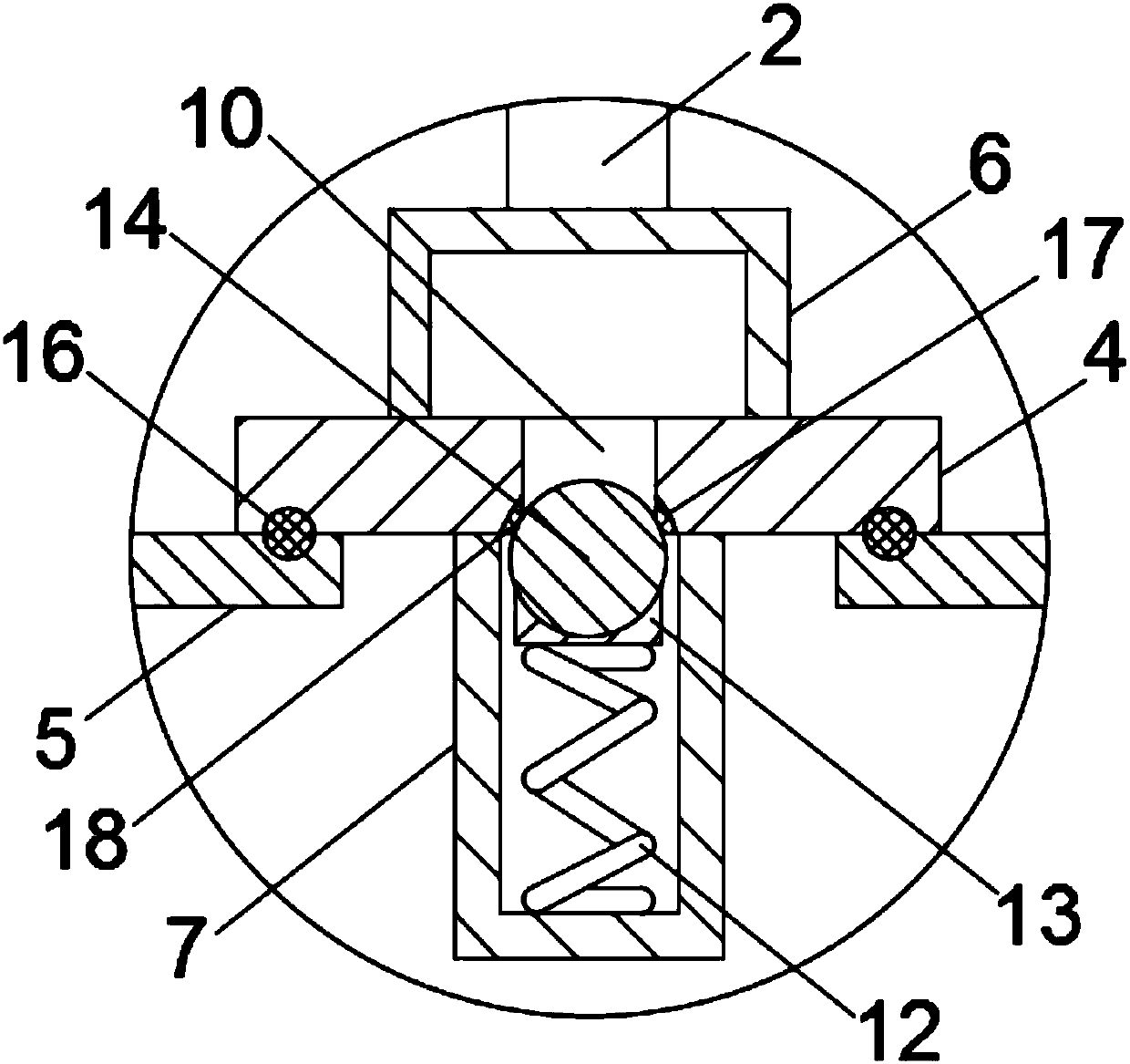
[0018] see Figure 1-3 , the present invention provides a technical solution: a constant pressure hydraulic control valve, including a valve body 1, an adjusting screw rod 2, a constant pressure device 3, a valve core 4 and a sealing frame 5, and the top of the valve body 1 is provided with a screw thread hole, the adjusting screw rod 2 is movably connected with the threaded hole through threads, the bottom of the adjusting screw rod 2 is fixed with the valve ...


PUM


Abstract

The invention discloses a constant pressure hydraulic control valve. The top of the valve body is provided with a threaded hole. An adjusting screw rod is movably connected with the threaded hole through the thread. The bottom of the adjusting screw rod is fixed to the valve core through a constant pressure device. The bottom of the valve core is Fit the sealing frame, the sealing frame is fixed to the inner wall of the valve body, the constant pressure device includes the water inlet tank, the water outlet tank and the sealing assembly, the adjusting screw is fixed on the top of the water inlet tank, the water inlet tank is fixed on the top of the valve core, the water inlet tank There are a number of water inlet holes evenly distributed on the outside, a through hole is provided in the middle of the valve core, the water inlet tank is connected with the water outlet tank through the through hole, the top of the water outlet tank is fixed with the valve core, and a number of water outlet holes are evenly distributed outside the water outlet tank, the sealing assembly Fixed inside the water outlet tank, the sealing assembly includes a compression spring, a fixed block and a sealing ball. This constant pressure hydraulic control valve can protect the valve body and the water pipe from overload through the constant pressure device, preventing the valve body and the water pipe from being damaged by water. Damaged by excessive pressure.

Description

technical field [0001] The invention relates to the technical field of hydraulic control valves, in particular to a constant pressure hydraulic control valve. Background technique [0002] The hydraulic control valve is a valve controlled by water pressure. The hydraulic control valve is composed of a main valve and its attached conduit, pilot valve, needle valve, ball valve and pressure gauge. According to different purposes, functions and places, it can be evolved into remote control float valve, pressure reducing valve, slow closing check valve, flow control valve, pressure relief valve, hydraulic electric control valve, water pump control valve, etc. [0003] Since the pressure of the water body in the water pipe is related to the output of the water body, when the pressure of the water body is too high, it is easy to cause damage to the water pipe, and the hydraulic control valve is connected to the water pipe, which may cause damage to the force control valve. Conten...

Claims


Application Information

Patent Timeline
Patent Type & Authority Applications(China)
IPC IPC(8): F16K1/04F16K1/46F16K17/04F16K17/168
CPCF16K1/04F16K1/46F16K17/0406F16K17/168
Inventor 林列谦
Owner 温州诚博阀门有限公司
Why Eureka
Try Eureka