
Optical remote sensing image terrain correction method based on in-canopy radiative transfer mechanism

A technology for optical remote sensing and terrain correction, which is applied in the direction of material analysis, scientific instruments, and measuring devices by optical means. It can solve problems such as limiting wide application and achieve the effect of improving application potential.

Active Publication Date: 2018-04-17
INST OF MOUNTAIN HAZARDS & ENVIRONMENT CHINESE ACADEMY OF SCI
View PDF0 Cites 8 Cited by
  • Summary
  • Abstract
  • Description
  • Claims
  • Application Information

AI Technical Summary

Problems solved by technology

However, radiative transfer in slope canopy is a highly nonlinear physical process, which satisfies the formula The assumption is too simple, so there is a large uncertainty in the D-S correction, which limits its wide application

Method used


Image

  • Optical remote sensing image terrain correction method based on in-canopy radiative transfer mechanism
  • Optical remote sensing image terrain correction method based on in-canopy radiative transfer mechanism
  • Optical remote sensing image terrain correction method based on in-canopy radiative transfer mechanism

Examples


Embodiment

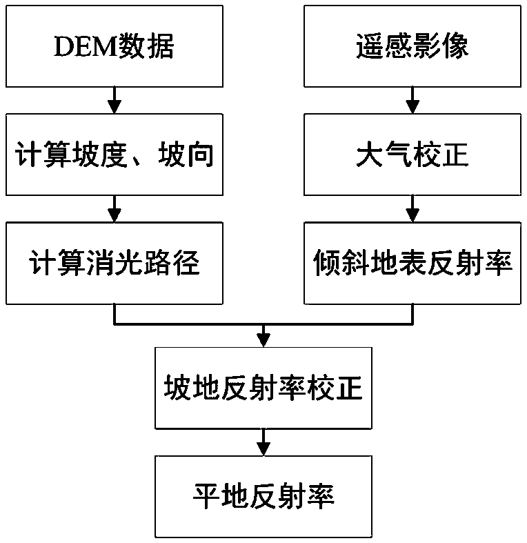
[0056] Such as figure 1 As shown, a topographic correction method for optical remote sensing images based on the radiative transfer mechanism within the canopy includes the following steps:

[0057] S1. Collect optical remote sensing images and DEM data of the target;

[0058] S2. Calculate the slope and aspect according to the DEM data, calculate the imaging geometry per pixel according to the image header file, and then calculate the flat or slope extinction path corresponding to each pixel according to the following formula,

[0059] S(θ)=1 / cos(θ)

[0060]

[0061] In the formula, θ and φ are the sun / observation zenith angle and azimuth angle respectively, α and β are the slope and aspect, respectively, and S and St are the normalized extinction paths of flat land and slope land under the same imaging geometric conditions, respectively;

[0062] At the same time, the atmospheric correction is performed on the remote sensing image to obtain the surface reflectance;

[...


PUM


Abstract

The invention relates to the technical field of optical remote sensing image terrain correction. From the perspective of a physical mechanism of photon-canopy-terrain interaction, through a simplifiedradiative transfer equation, the invention provides an optical remote sensing image terrain correction method which gives consideration to both physical mechanism completeness and mathematical form simplicity. The optical remote sensing image terrain correction method comprises the following steps: an optical remote sensing image and DEM (Digital Elevation Model) data of a target are acquired; according to the DEM data, slopes and orientations are calculated, and according to an image header file, a pixel-by-pixel imaging geometry is calculated; atmospheric correction is carried out on the remote sensing image, so that a surface reflectance is obtained; a flat ground or slope extinction path corresponding to each pixel is then calculated; with the surface reflectance and the extinction paths as an input, a slope reflectance is corrected into a flat ground reflectance. The terrain correction method disclosed by the invention is highly universal, has business operation capability, and can help increase the application potential of the satellite remote sensing technology in mountainous areas.

Description

technical field [0001] The invention relates to the technical field of topographic correction of optical remote sensing images, in particular to a topographic correction method of optical remote sensing images based on a radiation transmission mechanism within a canopy. Background technique [0002] Due to its macroscopic, dynamic and objective advantages, remote sensing technology has been widely used in many fields such as environmental monitoring, disaster prevention and mitigation, and agricultural production estimation. However, in mountainous areas with complex terrain, the terrain significantly affects the imaging process of optical remote sensing, so that the radiation signal of remote sensing observation contains too much non-ground factual terrain disturbance information. Suppressing the terrain information in the optical remote sensing signal to obtain the equivalent flat reflectance of the image (ie terrain correction) is the basic preprocessing technology for th...

Claims


Application Information

Patent Timeline
IPC IPC(8): G01N21/17
CPCG01N21/17G01N2021/1793
Inventor 尹高飞李爱农
Owner INST OF MOUNTAIN HAZARDS & ENVIRONMENT CHINESE ACADEMY OF SCI
Learn More